
Flow Routing
The Flow Routing method category is used to route the flow through the Distribution Canal element. If Time Lag Request Routing is selected on the containing AggDistributionCanal, only Time Lag Routing will be available in this category.
This method sets the available flow to equal the inflow after subtracting Canal Spillover and/or Canal Seepage if applicable.
Requests cannot be routed upstream when this method is selected. Therefore, this method is only available if No Routing is selected in the Request Routing category on the containing AggDistributionCanal.
There are no slots specific to this method.
Routes flow through the Distribution Canal element using a time lagged approach. Canal Spillover and/or Canal Seepage are subtracted from the Inflow before routing. Requests can be routed upstream when this method is selected only if Time Lag routing is selected in the Request Routing category on the containing AggDistributionCanal.
Slots Specific to This Method
Delivery Request
Type: SeriesSlot
Units: FLOW
Description: delivery request at the downstream end of the Canal element
Information:
I/O: Optional; Only used if routing requests.
Links: Usually linked to the Diversion Requested slot on a Water User or Total Diversion Requested on an Agg Diversion Site.
Ds Delivery Request
Type: SeriesSlot
Units: FLOW
Description: delivery requests from any downstream objects
Information: The DS Delivery Request is added to the Delivery Request and the sum is routed to the upstream end of the Distribution Canal element. Only used if routing requests.
I/O: Optional; usually set by propagation across a link
Links: DS Delivery Request is either automatically linked to the Routed Delivery Request slot on the downstream element, or (if there are no downstream elements) to the Downstream Delivery Request slot on the AggDistributionCanal object.
Lag Time
Type: TableSlot
Units: TIME
Description: lag time of the flow through the Distribution Canal element
Information: This must be an integer number of timesteps.
I/O: Optional; if not input, it is set to zero.
Links: Not linkable
Routed Delivery Request
Type: SeriesSlot
Units: FLOW
Description: routed delivery request at the upstream end of the Distribution Canal element
Information: The Routed Delivery Request is the sum of the DS Delivery Request and the Delivery Request, routed to the upstream end of the element. This slot is automatically linked, to either the DS Delivery Request of the upstream Canal element or to the Total Delivery Request on the AggDistributionCanal if there is no upstream element. Only used if routing requests. The Routed Delivery Request is always zero when the canal is draining (this only applies when a method is selected in the Canal Storage category).
I/O: Output only
Links: Automatically linked
Method Details
The Time Lag method is used to compute Available Flow. The necessary calculations are as follows:
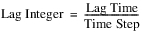
The value of Available Flow is the Inflow, after subtracting Canal Spillover and/or Canal Seepage. It is set at the timestep, t + Lag Integer, where t is the current timestep.
This method is a simple storage method that solves for Available Flow given current and previous Inflow values. The reach is broken up into a user-specified number of linked segments and flows are calculated for each segment. This method is almost identical to the Storage Routing method on the Reach object.
Slots Specific to This Method
Number of Segments in Reach
Type: ScalarSlot
Units: NOUNITS
Description: number of segments upstream to downstream
Information: This will determine the number of columns in the Segment Outflow table as well.
I/O: Required input
Links: Not linkable
Segment Outflow
Type: TableSeriesSlot
Units: FLOW
Description: segment outflow
Information: Available Flow is set as the outflow the last segment. The columns in this table will be resized to the number of segments input by the user, and the number of rows will be the number of timesteps in the run.
I/O: Output only
Links: Not linkable
Storage Time Coefficient
Type: ScalarSlot
Units: NOUNITS
Description: value that is divided by the result of the average flow and exponent to arrive at time in storage
Information: The units of this slot should be Volumeexponent (a value should be used that is in (ft3)exponent). This coefficient may be determined by trial and error, and should not be negative. The value must correspond to a flow value in cfs and storage time in hours, regardless of the user units on other slots.
I/O: Required input
Links: Not linkable
Storage Time Exponent
Type: ScalarSlot
Units: NOUNITS
Description: exponent of mean flow value.
Information: Usually between -1 and 1. The value must correspond to a flow value in cfs and storage time in hours, regardless of the user units on other slots.
I/O: Required input
Links: Not linkable
Method Details
The algorithm proceeds as follows:
1. If the previous Inflow value is not known, the method exits.
2. The outflow value for each segment from the previous timestep is checked for validity. There are then three possible scenarios:
– If the segment outflows are not valid and previous Available Flow is not valid, Available Flow is set equal to Inflow plus gain loss and the method exits.
– If the segment outflows are not valid, and previous Available Flow is valid, set all segment outflows equal to previous Inflow, and continue the routing method.
– If the segment outflows are valid, continue the method.
3. Find the mean interior flow from the previous timestep as the average of all segment outflows.
4. Find the time of storage in the reach based on the following empirical formula (in cfs):
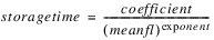
where storagetime is the time of storage in hours, coefficient and exponent are user input constants in the slots above, and meanfl is the average interior flow of the previous timestep.
Note: The storagetime calculation is always made with meanfl in units of cfs regardless of the user units on any flow slots. The values for Storage Time Coefficient and Storage Time Exponent should be set accordingly.)
The time in storage can be used as a conversion from storage to outflow.

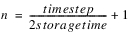
5. Find the number of routing phases, n. If the time of storage is greater than half of the simulation timestep, n is 1. Otherwise, n is calculated as follows:

If n is greater than 48 from this equation, n is set to 6.
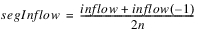
6. The inflow into the first segment for each routing phase is as follows:

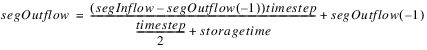
– For each routing phase, the outflow from each segment is as follows:

– This routing equation is based on the storage-outflow relation, storagetime, from above, and the continuity equation, as follows:

– The inflow into the next segment is the average of the segments previous and current outflows.
– The current timestep’s Available Flow for the object is equal to the last segment’s outflow.
This method is a simple storage method that solves for Available Flow given current and previous Inflow values. The reach is broken up into a user-specified number of linked segments and flows are calculated for each segment. This method differs from the Storage Routing method only in the determination of the storagetime value. In this method, the storage time exponent and coefficient are found from a table lookup based on flow instead of constant values. This method is almost identical to the Variable Storage Routing method on the Reach object.
Slots Specific to This Method
Flow Range
Type: TableSlot
Units: FLOW
Description: the ranges of flow rates corresponding to the Variable Storage Time Tables
Information: The number of flow ranges allowed in this table is currently limited to ten.
The columns of this table represent the maximum flow rate for a specific flow range, in ascending order, starting with 0 as the base. These columns are labeled “Flow Range 1 - 10”. The first column represents a range of flows from 0 to the value input by the user in the Flow Range 1 column.
The last flow range entered by the user should be a flow rate greater than any anticipated for the simulation; otherwise, a value of 0.0 will be used for the Variable Storage Time slots for flows outside of this range.
It is not necessary to use all ten columns of this table. Use only the columns needed to designate the desired flow ranges.
I/O: Required input
Links: Not linkable
Number of Segments in Reach
Type: ScalarSlot
Units: NOUNITS
Description: number of segments upstream to downstream
Information: This will determine the number of columns in the Segment Outflow table as well.
I/O: Required input
Links: Not linkable
Segment Outflow
Type: TableSeriesSlot
Units: FLOW
Description: segment outflow
Information: Available Flow is set as the outflow from the last segment. The columns in this table will be resized to the number of segments input by the user, and the number of rows will be the number of timesteps in the run.
I/O: Output only
Links: Not linkable
Variable Storage Time Coefficient
Type: SeriesSlot
Units: NOUNITS
Description: value that is divided by the result of the average flow and exponent to arrive at time in storage
Information: The units of this slot should be Volumeexponent (a value should be used that is in (ft3)exponent).
I/O: Output only
Links: Not linkable
Variable Storage Time Coefficient Table
Type: Tableslot
Units: NOUNITS
Description: Variable Storage Time Coefficient for each specific Flow Range
Information: The columns of the table correspond to the flow ranges defined in Flow Range. The values must correspond to a flow value in cfs and storage time in hours, regardless of the user units on other slots.
I/O: Required input
Links: Not linkable
Variable Storage Time Exponent
Type: SeriesSlot
Units: NOUNITS
Description: exponent of mean flow value.
Information: Usually between -1 and 1.
I/O: Output only
Links: Not linkable
Variable Storage Time Exponent Table
Type: Tableslot
Units: NOUNITS
Description: Lag times for each specific Flow Range
Information: The columns of the table correspond to the flow ranges defined in Flow Range. The values must correspond to a flow value in cfs and storage time in hours, regardless of the user units on other slots.
I/O: Required input
Links: Not linkable
Method Details
The algorithm proceeds as follows:
1. If the previous Inflow value is not known, the method exits.
2. The outflow value for each segment from the previous timestep is checked for validity. There are then three possible scenarios:
– If the segment outflows are not valid and previous Available Flow is not valid, Available Flow is set equal to Inflow plus gain loss and the method exits.
– If the segment outflows are not valid, and previous Available Flow is valid, set all segment outflows equal to previous Inflow, and continue the routing method.
– If the segment outflows are valid, continue the method.
3. Find the mean interior flow from the previous timestep as the average of all segment outflows.
4. Find the time of storage in the reach based on the following empirical formula (in cfs):

where storagetime is the time of storage in hours, coefficient and exponent are user input constants in the slots above, and meanfl is the average interior flow of the previous timestep.
Note: The storagetime calculation is always made with meanfl in units of cfs regardless of the user units on any flow slots. The values in the Variable Storage Time Coefficient Table and Variable Storage Time Exponent Table should be set accordingly.)
The time in storage can be used as a conversion from storage to outflow:

5. Find the number of routing phases, n. If the time of storage is greater than half of the simulation timestep, n is 1. Otherwise, n is calculated as:
If n is greater than 48 from this equation, n is set to 6.
6. The inflow into the first segment for each routing phase is as follows:
– For each routing phase, the outflow from each segment is as follows:
– This routing equation is based on the storage-outflow relation, storagetime, from above, and the continuity equation, as follows:

– The inflow into the next segment is the average of the segments previous and current outflows
– The current timestep’s Available Flow for the object is equal to the last segment’s outflow.
Revised: 01/10/2022