View the RiverWare Model Schematic
The model schematic shows the model components (objects and links) that form the network of the RiverWare hydrologic model. The various Object types are listed in the table below. Links represent data connections between data on the Objects. An image, such as a map, may be displayed with the schematic.
Use the following actions to navigate the model schematic.
• Zoom in or out. Right-click in the display panel and select the desired zoom level.
• Pan. Use the middle mouse button and Scroll bars to pan through the schematic.
• View links. Hover over the lines on the workspace to see tooltips describing the links.
• Select Open in Separate Window to show the schematic in a separate display. This allows it to be visible even when another RiverWISE tab is selected.
Icon | Description | Icon | Description |
|---|---|---|---|
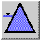 | Storage Reservoir Reservoir with Release and spillways; no hydropower. Pool Elevation is a function of Storage. | 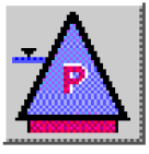 | Level Power Reservoir Reservoir with hydropower (turbine release) and spillways; Pool Elevation is a function of Storage. |
 | Slope Power Reservoir Reservoir with hydropower and spillways. Storage is level storage plus wedge storage. |  | Pumped Storage Reservoir Reservoir with reversible pump-turbines that may generate or pump at each timestep. |
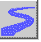 | Reach Models routing in a river section; acts as node for diversions and return flows; models gains, losses. | 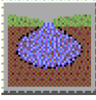 | Groundwater Models head based flow and storage of water in ground, groundwater-surface water interaction. |
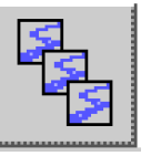 | Aggregate Reach Aggregation of multiple Reach objects. | Aquifer A deep, fully saturated, often confined groundwater system. | |
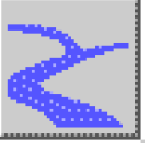 | Confluence A flow junction with two Inflows and a single Outflow. |  | Stream Gage Represents a gauge location in a river system; no simulated process. |
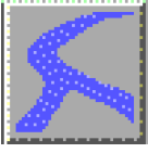 | Bifurcation A flow junction with two Outflows and a single Inflow. | 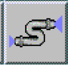 | Pipeline Models pipe flow (pressurized). |
 | Water User Diverts water from a Reach or Reservoir, models consumptive use and return flows. |  | Pipe Junction Models a junction in pressurized flow system. |
 | Aggregate Diversion Site Contains Water Users; diverts from Reach or Reservoir; models consumptive user and return flow. |  | Inline Pump Models a booster pump station; calculates added head and power consumed. |
 | Diversion Diverts water from a Reservoir or Reach. | 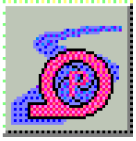 | Inline Power plant Models power generation in reach with no storage, also called run-of-river power plant. |
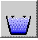 | Canal Models bi-directional conveyance channel by gravity flow between two reservoirs. | 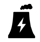 | Power Plant Diversion Models the diversion and consumption of water by a Power Plant, often for cooling. |
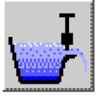 | Aggregate Distribution Canal Routes flows through multiple canal reaches from Diversion to Water users, and routes demands | 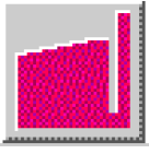 | Thermal Models economics of thermal power system and thermal replacement value of hydropower. |
 | Control Point Point of regulation; for example, for channel capacity for floods or instream flow regulation. | 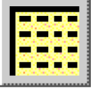 | Data Object Container for user-configured data and custom slots; for example, expressions for user-defined calculations. |
Revised: 01/10/2022