Inline Power
These methods determine how power is calculated.
This default method does no power calculations.
There are no slots specific to this method.
This method looks up the power from a table based on the flow rate through the turbines. It uses a linear interpolation to calculate the power. It is important to have enough data values if the power curve is not linear.
Slots Specific to This Method
Energy
Type: Series Slot
Units: Energy
Description: Product of power generated and the timestep length
Information:
I/O: Output only
Links: Usually not linked.
Hydro Capacity
Type: Series Slot
Units: power
Description: Maximum power capacity of the inline power plant.
Information: This slot is utilized in optimization
I/O: Output only
Links: Linkable, usually to the same slot on the Thermal object.
Power
Type: Series Slot
Units: POWER
Description: Power generated by flow through the units
Information: Calculated using the PowerFlow and Flow Vs Power Table
I/O: Output only
Links: Not linkable
Flow vs Power Table
Type: Table Slot
Units: Flow vs. Power
Description: Power produced at that given flow rate.These tables should include any maximum or minimum flow rates through the plant and the corresponding values. In theory, the upstream control should account for these maximums and minimums but having them in the table is more complete.
Information:
I/O: Required input
Links: Not linkable
Method Details
When the Specify Flows method (see Specify Flows) is selected, the following process occurs.
1. The Power slot is computed via linear interpolation of the Flow vs Power Table using the PowerFlow intermediate value. See Inline Turbine Release and Bypass for details on the method used.
2. Energy is then computed as the product of Power and the timestep length.
3. The Hydro Capacity slot is computed as the Max Turbine Release slot value multiplied by the Power Plant Cap Fraction.
When the Flow Tables method (see Flow Tables) is selected, the following process occurs.
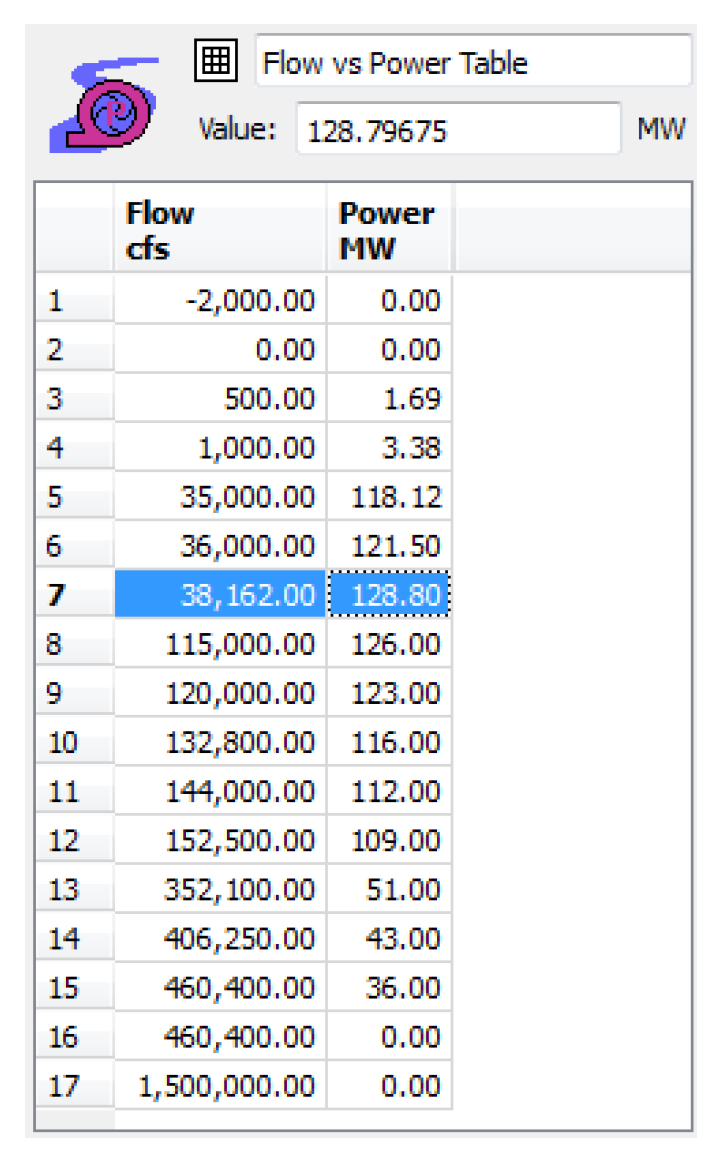
1. A sample Flow vs Power Table is shown in Figure 16.1. This method uses the PowerFlow intermediate variable and MinTRatMaxGen; see Flow Tables. The maximum of the PowerFlow and the MinTRatMaxGen is looked up on Flow vs Power Table to get the tempCapacity. The tempCapacity is then multiplied by the Power Plant Cap Fraction and set on the Hydro Capacity slot.
Figure 16.1 

2. The PowerFlow is then looked up on the Flow vs Power Table to get the tempHydropower.

3. Energy is then computed as the product of Power and the timestep length.
With this method, you specify the turbine capacity and generating capacity for each unit, and for each timestep, you optionally specify the fraction of capacity at which each unit is generating or specify the Unit Turbine Release. The method then calculates the Unit Power and Unit Energy as well as the total plant Turbine Release, Power and Energy. This method cannot be selected in combination with the Flow Tables method in the Inline Turbine Release and Bypass category.
Slots Specific to This Method
Number of Units
Type: Scalar Slot
Units: None
Description: The number of units (generators) in the plant
Information: This must be an integer greater than or equal to 1. If the value is not an integer, RiverWare rounds the value down to the nearest integer.
I/O: Required input
Links: Not linkable
Unit Capacity
Type: Table Slot
Units: Flow, Power
Description: The turbine capacity and generating capacity of each unit
Information: The table has a row for each unit. The first column is the unit turbine capacity, the second column is the unit generating capacity. At the start of a run, RiverWare automatically resizes the number of rows to match the value in the Number of Units slot, if they do not match already.
I/O: Unit generating capacity (second column) is required input. Unit turbine capacity (first column) is optional input.
Links: Not linkable
Unit Generation Fraction
Type: Agg Series Slot
Units: Fraction
Description: The slot has one column for each unit and represents the fraction of full capacity at which the unit is generating.
Information: If the corresponding Unit Turbine Release is specified (input or rules) and the unit turbine capacity is provided (Unit Capacity slot) then the value is calculated as the Unit Turbine Release divided by unit turbine capacity. Otherwise, if no value is provided, it defaults to 1 (generating at full capacity). A value outside the range of 0 to 1 causes the run to terminate with an error message.
Note: If this slot is set by rules, the value in the first column (Unit 1) must be set in order to cause the Inline Power object to redispatch with the new Unit Generation Fraction value. Setting a value with rules in one of the other columns without setting the first column does not cause the object to redispatch. You cannot specify both Unit Turbine Release and Unit Generation Fraction for the same unit.
I/O: Input or Output; if not input and if Unit Turbine Release is not input, then it defaults to 1
Links: Not linkable
Unit Turbine Release
Type: Agg Series Slot
Units: Flow
Description: The flow through each turbine, one column for each unit (turbine)
Information: If not specified (input or rules), the value is calculated as the unit turbine capacity (Unit Capacity slot) multiplied by the Unit Generation Fraction. If the unit turbine capacity is not provided, the value is NaN. You cannot specify both Unit Turbine Release and Unit Generation Fraction for the same unit.
I/O: Input or output
Links: Not linkable
Unit Power
Type: Agg Series Slot
Units: Power
Description: The power that is generated by each unit, Unit Capacity multiplied by Unit Generation Fraction
Information: One column for each unit
I/O: Output only
Links: Not linkable
Unit Energy
Type: Agg Series Slot
Units: Energy
Description: The energy that is generated by each unit, Unit Power multiplied by the timestep length
Information: One column for each unit
I/O: Output only
Links: Not linkable
Power
Type: Series Slot
Units: Power
Description: The total power generation of the plant, the sum of Unit Power for all units
Information:
I/O: Output only
Links: Linkable
Energy
Type: Series Slot
Units: Energy
Description: The total energy generation of the plant, Power multiplied by the timestep length
Information:
I/O: Output only
Links: Linkable
Method Details
You must specify the Number of Units scalar slot. This must be an integer greater than or equal to 1. If the value is not an integer, RiverWare rounds the value down to the nearest integer. At the start of the run, RiverWare sets the number of rows in the Unit Capacity slot, and number of columns in the Unit Generation Fraction, Unit Turbine Release, Unit Power, and Unit Energy slots to match the value in the Number of Units scalar slot.
Note: This could delete rows or columns with data if the Number of Units value is reduced.
To initially add rows and columns to these slots, first set the Number of Units scalar slot to the desired value. Then run the model. The run will terminate, but the table and Agg series slots will be resized to the appropriate number of rows and columns. Then the required input values can be entered in the Unit Capacity and Unit Generation Fraction or Unit Turbine Release slots.
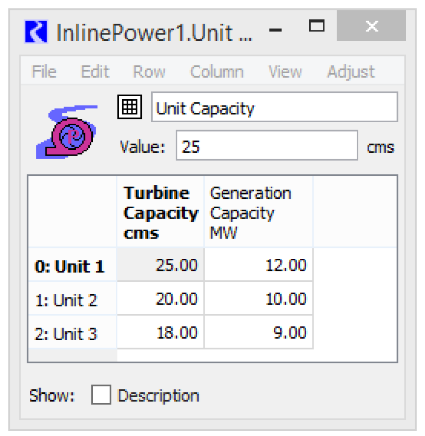
You must specify the generating capacity value for each unit in the Unit Capacity table slot. The turbine capacity values are optional inputs. These are static, physical characteristic parameters. Figure 16.2 is an example.
Figure 16.2

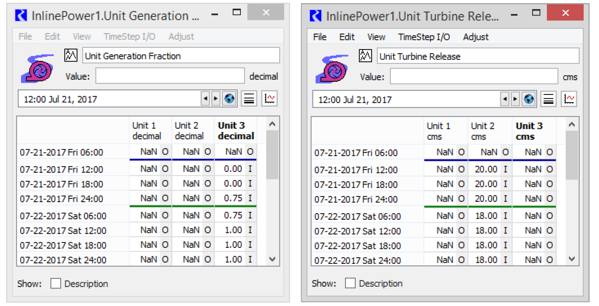
You can optionally provide time series values (input or rules) for each unit in the Unit Generation Fraction and Unit Turbine Release Agg series slots. If values are not provided for Unit Turbine Release or Unit Generation Fraction, Unit Generation Fraction defaults to 1. You cannot specify both Unit Generation Fraction and Unit Turbine Release for the same unit. See Figure 16.3.
Figure 16.3

Note: When setting the Unit Generation Fraction or Unit Turbine Release values by rules, only values set in the “Unit 1” column trigger dispatching or redispatching of the Inline Power object. Values set in subsequent columns do not cause the object to dispatch.
The method then performs the following computations.
FOR each unit i
IF Unit Turbine Releasei is input or set by rules
Use the specified Unit Turbine Release to calculate the Unit Generation Fraction, but first check against the unit capacity.
IF Unit Turbine Capacityi is input
IF 

Abort with and error message.
ELSE

END IF
ELSE
If there is no unit turbine capacity, then Unit Generation Fraction will just get set to 1.

END IF
ELSE (Unit Turbine Releasei is not specified)
IF Unit Turbine Capacityi is input
Unit Generation Fraction will have been set to 1 if not input or set by rules.

ELSE
Unit Turbine Release cannot be calculated so it will remain as NaN.
END IF
END IF


END FOR
The Power and Energy slots are then calculated as the sum of the Unit Power and Unit Energy.


The total plant Turbine Release can be calculated by this method only if every unit has unit turbine capacity (Unit Capacity slot), Unit Turbine Release, or both specified (input or set by rules). If one or more units has neither of these values specified, Turbine Release and Bypass is not set by this method. The values come from the selected Inline Turbine Release and Bypass method. If Turbine Release is set by this method, it is checked against plant limits, and then Bypass is also set.
IF Turbine Release can be calculated

IF 

Abort with an error message
END IF
IF Min Bypass is specified (input or rules)
IF 

Abort with an error message
END IF
ELSE
IF 

Abort with an error message
END IF
END IF

ELSE (Total plant Turbine Release cannot be calculated)
Leave Turbine Release and Bypass as set by the Inline Power Turbine Release and Bypass method.
END IF
Revised: 07/17/2020