
Gain Loss
This method category is used to model gains and/or losses in the Reach. It is available, as well as all the user methods contained within it, for all Routing methods.
Note: The equations given for each Gain Loss method may be slightly modified if the Previous Flow Average method is selected in the Apply Gain Loss category.
This is the default method. No calculations are performed and there are no slots associated with this method. It should be used if you do not want to model gains or losses.
Used when the gain or loss parameters do not vary with respect to time.
Slots Specific to This Method
GainLoss
Type: Table
Units: FLOW
Description: represents a given amount of flow that is gained or lost regardless of the flow rate in the reach
Information: A positive number represents a gain while a negative number represents a loss.
I/O: Optional; defaults to 0.0 if not input.
Links: Not linkable
GainLoss Coeff
Type: Table
Units: DECIMAL
Description: represents a given percentage of flow in the reach that is gained or lost
Information: Must be a number between -1 and 1. For example, a value of -0.1 means that 10% of the flow in the reach is lost. If solving upstream, must be greater than -1.
I/O: Optional; defaults to 0.0 if not input.
Links: Not linkable
Total GainLoss
Type: Series
Units: FLOW
Description: represents the total amount of flow that is gained or lost in a reach for a given timestep
Information: Applied to the bottom of the reach (it is added to the outflow value calculated from the Routing method).

I/O: Output only
Links: Not linkable
Used when a time series range of gain or loss parameters is required.
Slots Specific to This Method
Variable GainLoss
Type: Series
Units: FLOW
Description: represents a given amount of flow that is gained or lost regardless of the flow rate in the reach
Information: A positive number represents a gain while a negative number represents a loss.
I/O: Optional; defeats to 0.0 if not input.
Links: Not linkable
Variable GainLoss Coeff
Type: Series
Units: DECIMAL
Description: represents a given percentage of flow in the reach that is gained or lost
Information: Must be a number between -1 and 1. For example, a value of -0.1 means that 10% of the flow in the reach is lost. If solving upstream, must be greater than -1.
I/O: Optional; defaults to 0.0 if not input.
Links: Not linkable
Total GainLoss
Type: Series
Units: FLOW
Description: represents the total amount of flow that is gained or lost in a reach for a given timestep
Information: Applied to the bottom of the reach (it is added to the outflow value calculated from the Routing method).

I/O: Output only
Links: Not linkable
Used to calculate the gain/loss parameters based on season and a range of flow rates.
Tip: The Periodic and Flow based Gain Loss performs similar computations to this method, but is easier to setup. Consider using that method instead!
Slots Specific to This Method
Date Range
Type: Table
Units: NO UNITS
Description: the actual days of the 366 day year that correspond to the Number of Seasons
Information: Each column of this table corresponds to a particular season and are labeled Season 1 - 12. The two rows labeled 0 and 1 respectively represent the beginning day and ending day of the season column. The allowable range for these inputs is 1 - 366. It is recommended to cover the entire year within the Number of Seasons columns quantified in that slot.
I/O: Required input
Links: Not linkable
Flow Range
Type: Table
Units: FLOW
Description: the ranges of flow rates corresponding to the Variable GainLoss Coeff Table and Variable GainLoss Table
Information: The number of flow ranges allowed in this table is currently limited to 10.
The columns of this table represent, in ascending order, the maximum flow rate for a specific flow range, starting with 0 as the base. These columns are labeled Flow Range 1 – 10.
Therefore, the first column represents a range of flows from 0 to the value input by the user in the Flow Range 1 column.
The last flow range entered by the user should be a flow rate greater than any anticipated for the simulation; otherwise, a value of 0.0 will be used for flows outside of this range.
It is not necessary to use all 10 columns of this table; use only the columns needed to designate the desired flow ranges.
I/O: Required input
Links: Not linkable
Number of Season
Type: Scalar
Units: NO UNITS
Description: the number of seasons corresponding to the Variable GainLoss Coeff Table and Variable GainLoss Table
Information: The maximum number of seasons currently allowed in RiverWare is 12.
I/O: Required input
Links: Not linkable
Variable GainLoss
Type: Series
Units: FLOW
Description: represents a given amount of flow that is gained or lost regardless of the flow rate in the reach
Information: A positive number represents a gain while a negative number represents a loss.
I/O: Optional; if not input, it is obtained from the Variable GainLoss Table.
Links: Not linkable
Variable GainLoss Coeff
Type: Series
Units: DECIMAL
Description: represents a given percentage of flow in the reach that is gained or lost
Information: Must be a number between -1 and 1. For example, a value of -0.1 means that 10% of the flow in the reach is lost. If solving upstream, must be greater than -1.
I/O: Optional; if not input, it is obtained from the Variable GainLoss Coeff Table.
Links: Not linkable
Variable GainLoss Coeff Table
Type: Table
Units: TIME
Description: Variable GainLoss Coeff values for each specific Date Range and Flow Range
Information: The columns of the table correspond to the flow ranges defined in Flow Range, and the rows correspond to the seasons defined in Date Range.
I/O: Required input
Links: Not linkable
Variable GainLoss Table
Type: Table
Units: TIME
Description: Variable GainLoss values for each specific Date Range and Flow Range
Information: The columns of the table correspond to the flow ranges defined in Flow Range, and the rows correspond to the seasons defined in Date Range.
I/O: Required input
Links: Not linkable
Total GainLoss
Type: Series
Units: FLOW
Description: represents the total amount of flow that is gained or lost in a reach for a given timestep
Information: Applied to the bottom of the reach (it is added to the outflow value calculated from the Routing method).

I/O: Output only
Links: Not linkable
This method is similar to the Seasonal Gain Loss Flow Table method except the data is based on the day of the year and the tables are interpolated to find values for gain-loss and the gain-loss coefficient.
The Periodic and Flow based Gain Loss performs similar computations to this method, but is easier to setup. Consider using that method instead!
Slots Specific to This Method
Interpolated GainLoss
Type: Series
Units: FLOW
Description: represents a given amount of flow that is gained or lost regardless of the flow rate in the reach
Information: A positive number represents a gain while a negative number represents a loss. It is calculated by double interpolation of the Interpolated GainLoss Table
I/O: Output only
Links: Not linkable
Interpolated GainLoss Coeff
Type: Series
Units: FRACTION
Description: represents a given percentage of flow in the reach that is gained or lost
Information: Must be a number between -1 and 1. For example, a value of -0.1 means that 10% of the flow in the reach is lost. It is calculated by double interpolation of the Interpolated GainLoss Coeff Table.
I/O: Output only
Links: Not linkable
Interpolated GainLoss Coeff Table
Type: Table
Units: TIME VS. Flow VS. fraction
Description: A table relating the day of the year, flow rate, and the gain-loss coefficient
Information: Data must be entered in blocks of increasing flow for each given day for the interpolation method to work correctly. January 1 is represented by a 1, February 1 as 32, and so on. Following is an example table.
Day of Year | Flow Rate | GainLoss Coeff |
|---|---|---|
1 | 500 | .01 |
1 | 550 | .02 |
1 | 600 | .03 |
32 | 500 | .025 |
32 | 550 | .03 |
32 | 600 | .035 |
60 | 500 | .03 |
60 | 550 | .035 |
60 | 600 | .04 |
I/O: Required input
Links: Not linkable
Interpolated GainLoss Table
Type: Table
Units: Time vs. flow vs. flow
Description: a table relating the day of the year, the flow rate and the gain-loss value
Information: Data must be entered in blocks of increasing flow for each given day for the interpolation method to work correctly. January 1 is represented by a 1, February 1 as 32, and so on. The table is set up in the same manner as the Interpolated GainLoss Coeff Table (shown above).
I/O: Required input
Links: Not linkable
Total GainLoss
Type: Series
Units: FLOW
Description: represents the total amount of flow that is gained or lost in a reach for a given timestep
Information: Applied to the bottom of the reach (it is added to the outflow value calculated from the Routing method).
I/O: Output only
Links: Not linkable
Method Details
A 3‑D interpolation method is used to calculate a value for Interpolated GainLoss and Interpolated GainLoss Coeff using the Interpolated GainLoss Table and Interpolated GainLoss Coeff Table, respectively. Once these values are calculated Total GainLoss is set as follows:

This method is used to model loss in a reach; it does not allow gain. Loss is calculated as base flow rate plus a proportion of the flow above the base. Loss is limited to be less than a maximum value. This method will be available for all Routing methods except Time Lag routing.
Slots Specific to This Method
Base Loss
Type: Periodic
Units: Time vs Flow
Description: Represents an amount of flow that is lost regardless of the flow rate in the reach. The method will limit the total loss to be less than or equal to the flow in the reach.
Information: A positive number represents a loss. A negative number results in an error.
I/O: Required input
Links: Not linkable
Loss Fraction above Base
Type: Periodic
Units: Time vs Decimal
Description: This slot represents a fraction of the flow above the Base Loss that will be lost
Information: A positive number represents a loss; the value must be between 0 and 1 or an error is issued.
I/O: Required input
Links: Not linkable
Maximum Loss
Type: Scalar
Units: FLOW
Description: The maximum loss that can occur from the reach
Information: If not input, no maximum is used
I/O: Optional Input
Links: Not linkable
Total GainLoss
Type: Series
Units: FLOW
Description: Represents the total amount of flow that is gained or lost in a reach for a given timestep
Information: A positive number represents a gain, a negative number represents a loss. The Total GainLoss is applied to the bottom of the reach (it is added to the outflow value calculated from the Routing method). In this method, a loss is represented by a negative number.
I/O: Output only
Links: Not linkable
Method Details
At the beginning of the method, the values for Base Loss and the Loss Fraction above Base are taken from the periodic slots and checked. As is typical with periodic slots, these slots can be configured to either lookup or interpolate. If either is invalid, the run terminates with an error. If the Base Loss is less than zero, the run terminates with an error. If the Loss Fraction above Base is less than 0 or greater than 1, the run terminates with an error.
On a reach, the Total GainLoss slot is used by other GainLoss methods. As a result, this method follows the same convention where a negative Total GainLoss represents a loss. Also, the flow used by the method is the flow in the reach after the routing has occurred. Thus, the Total GainLoss is the base loss plus the fractional loss associated with the flow above the base. Because the flow could be less than the base, the following formula is necessary to calculate the loss:
If Maximum Loss is NaN, then the Total GainLoss is set equal to the negative of the tempLoss value.
Otherwise, there is a valid Maximum Loss and the Total GainLoss is then set as follows:

This method is used to model gain and/or loss in a reach. The gain and loss values are entered as periodic data for a given time range. Gains are entered as positive values and losses are entered as negative values. This method will be available for all Routing methods except Time Lag routing.
Slots Specific to This Method
Periodic GainLoss
Type: Periodic
Units: Time vs Flow
Description: Represents an amount of flow that is gained or lost regardless of the flow rate in the reach.
Information: A positive number represents a gain. A negative number results in a loss.
I/O: Required input
Links: Not linkable
Total GainLoss
Type: Series
Units: FLOW
Description: Represents the total amount of flow that is gained or lost in a reach for a given timestep
Information: A positive number represents a gain, a negative number represents a loss. The Total GainLoss is applied to the bottom of the reach (it is added to the outflow value calculated from the Routing method). In this method, a loss is represented by a negative number.
I/O: Output only
Links: Not linkable
Method Details
At the beginning of the method, the value for Periodic GainLoss is taken from the periodic slot and checked. As is typical with periodic slots, this slot can be configured to either lookup or interpolate. If the value is invalid, the run terminates with an error.
This method follows the same convention as other GainLoss methods where a positive Total GainLoss represents a gain.

This method models Gain and Loss as a variable flow rate and fraction of the routed flow. Both the flow rate and the fraction are based on a date and flow rate, or could be specified by input or rules
Slots Specific to This Method
Periodic Gain Loss Table
Type: Periodic Slot with Numeric Header
Units: Header = Flow, Values = Flow
Description: The matrix that describes the amount of flow that should be gained or lost.
Information: This table has a column map, which means that each column has an associated numerical value (with units) displayed as the column label.
Columns are added and deleted from this table using the Column menu. User units, scale, type, and precision for the column map (that is, the column heading values) are defined in the unit scheme for Flow unit types. Column map values are set by selecting Column, then Set Column Value.
hen a column value is changed, the columns reorder to ensure the column values are increasing, from left to right. The left-most set of values should represent the minimum flow in the Reach. The right-most set of values should represent the largest flow expected. Values are interpolated across columns.
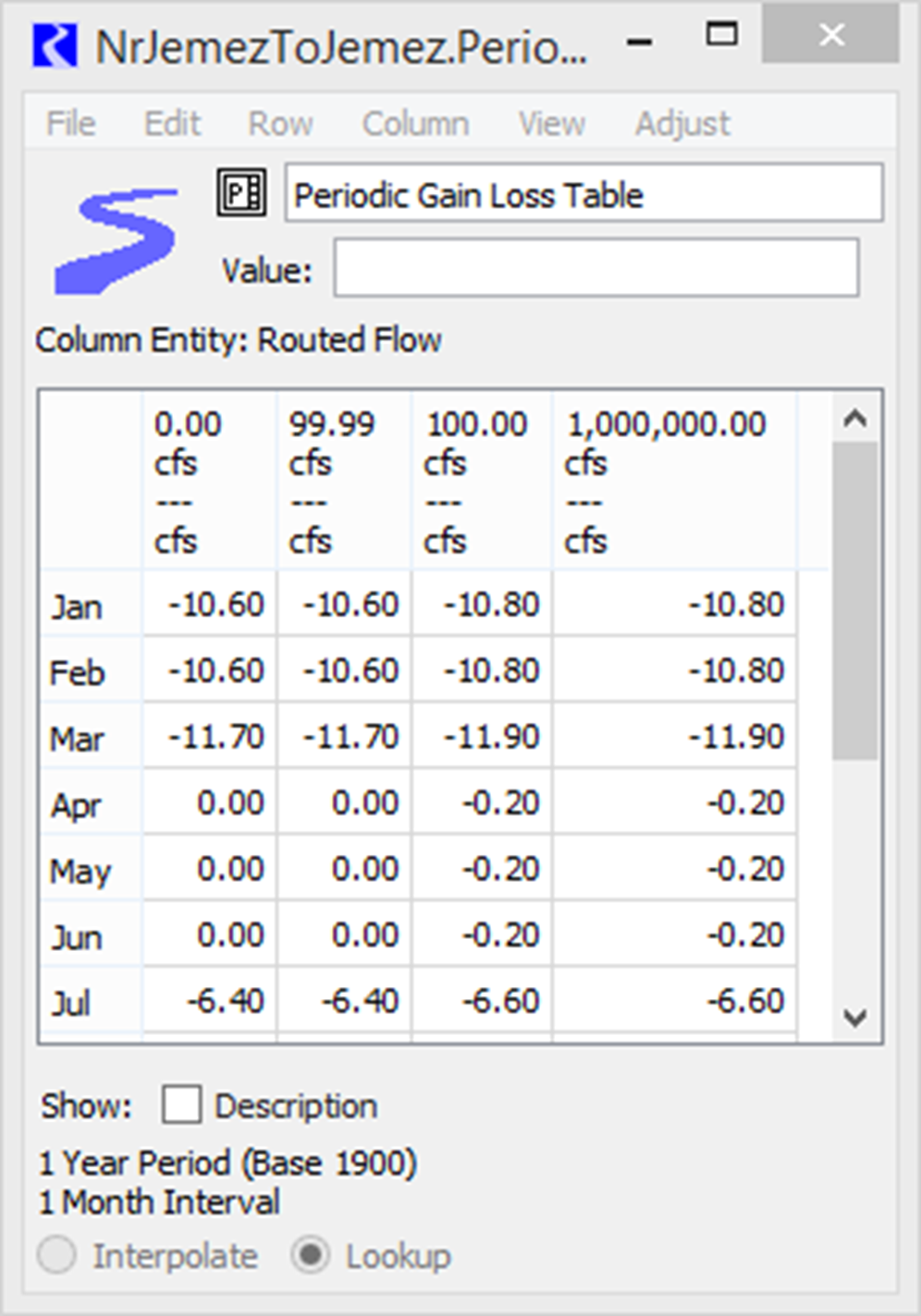
The configuration of the slot controls how values are accessed across rows (interpolate or lookup). Seen Figure 23.1 for a sample. Extra columns have been added to look up across flow ranges.
I/O: Required input
Links: Not linkable
Figure 23.1 Screenshot of a sample Periodic Gain Loss Table
Periodic Gain Loss Coeff Table
Type: Periodic Slot with Numeric Header
Units: Header = Flow, Values = Fraction
Description: The matrix defining the percentage of the routed flow that should be gained or lost.
Information: This table has a column map, which means that each column has an associated numerical value (with units) displayed as the column label.
Columns are added and deleted from this table using the Column menu. User units, scale, type, and precision for the column map (that is, the column heading values) are defined in the unit scheme for Flow unit types. Column map values are set by selecting Column, then Set Column Value.
When a column value is changed, the columns reorder to ensure the column values are increasing, from left to right. The left-most set of values should represent the minimum flow in the Reach. The right-most set of values should represent the largest flow expected. Values are interpolated across columns.
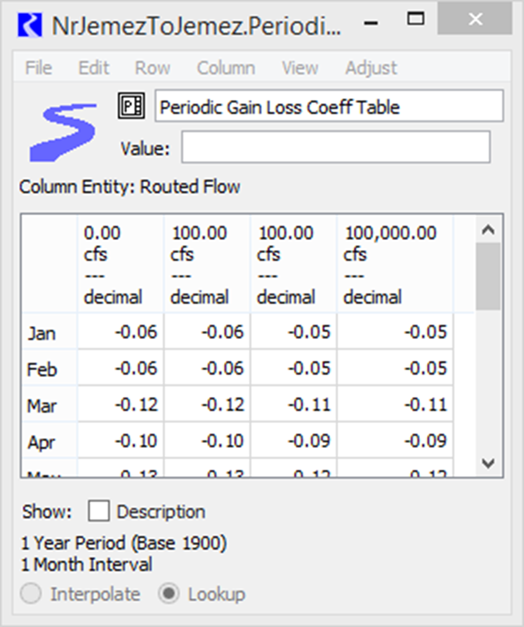
The configuration of the slot controls how values are accessed across rows (interpolate or lookup). See Figure 23.2 for a sample. Extra columns have not been added to allow it to interpolate across flow ranges.
I/O: Required input
Links: Not linkable
Figure 23.2 Screenshot of a sample Periodic Gain Loss Coeff Table
Variable GainLoss
Type: Series
Units: FLOW
Description: represents a given amount of flow that is gained or lost regardless of the flow rate in the reach
Information: A positive number represents a gain while a negative number represents a loss.
I/O: Optional; can be input if needed. More likely it is obtained from the Periodic GainLoss Table.
Links: Linkable
Variable GainLoss Coeff
Type: Series
Units: FRACTION
Description: represents a given percentage of flow in the reach that is gained or lost
Information: Should be a number between -1 and 1. For example, a value of -0.1 means that 10% of the flow in the reach is lost. If solving upstream, it must be greater than -1.
I/O: Optional; can be input if needed. More likely it is obtained from the Periodic GainLoss Coeff Table.
Links: Not linkable
Total GainLoss
Type: Series
Units: FLOW
Description: represents the total amount of flow that is gained (+value) or lost (- value) in a reach for a given timestep
Information: Applied to the bottom of the reach (it is added to the outflow value calculated from the Routing method).
I/O: Output only
Links: Not linkable
Method Details
The method computes the Total Gain Loss as follows:
The flow to use is provided by the routing method as the “Routed Flow.”
flow = RoutedFlow
Variable Gain Loss = Periodic Gain Loss Table [timestep, flow]
Variable Gain Loss Coeff = Periodic Gain Loss Coeff Table [timestep, flow]
Total Gain Loss = Variable Gain Loss Coeff * flow + Variable Gain Loss
Note: When solving upstream, the computation is iterative as the gain loss depends on the upstream routed flow, which is what is what is being computed. Convergence is defined on the Outflow slot. Max iterations is based on the simulation max iterations.
The Total GainLoss is returned to the dispatch method where it is used in the mass computation. This method follows the same convention as other GainLoss methods where a positive Total GainLoss represents a gain.
Revised: 08/04/2020