Rulebased Simulation
A modified version of the Model Run Analysis—Simulation dialog, which is available when the Simulation controller is active, is available when the Rulebased Simulation controller is active. The Rulebased Simulation version of the Model Run Analysis—Simulation dialog is called the Model Run Analysis—Rulebased Simulation dialog. It provides important information regarding slot priorities, determination of dispatch methods, and propagation of the effects of rules across a model. It is a diagnostic tool to be used in conjunction with the regular diagnostics to debug rules and verify that a run has solved as expected.
Main Analysis Dialog
The Model Run Analysis—Rulebased Simulation dialog is opened by selecting Model Run Analysis from the Utilities menu or selecting the Model Run Analysis toolbar button. Figure 2.4 shows a sample dialog.
 Figure 2.4 shows a sample dialog.
 Figure 2.4
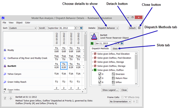
For each object at each timestep, the cells provide information about the dispatch state of the object. The five possible dispatch states and their icons are as follows:
•  Not Dispatched. The known and unknown slots for the timestep did not meet the conditions of any method on the dispatch table for the object.
 Not Dispatched. The known and unknown slots for the timestep did not meet the conditions of any method on the dispatch table for the object.
•  Dispatched But Did Not Solve. Conditions of a single dispatch method were met, the method dispatched, but the object did not solve completely (background is yellow).
 Dispatched But Did Not Solve. Conditions of a single dispatch method were met, the method dispatched, but the object did not solve completely (background is yellow).
•  Dispatched and Solved Based Entirely on User Input Values. Conditions of a single method were met from user input; the method dispatched, and the object solved completely.
 Dispatched and Solved Based Entirely on User Input Values. Conditions of a single method were met from user input; the method dispatched, and the object solved completely.
•  No Dispatch conditions. The object has no entries on its dispatch table; the object has no dispatch conditions (e.g., Thermal Object), or the model has not been run.
 No Dispatch conditions. The object has no entries on its dispatch table; the object has no dispatch conditions (e.g., Thermal Object), or the model has not been run.
•  Dispatched and Solved Based on Highest Priority Known Values - Conditions of a single method were met by prioritizing the slots, the method dispatched, and the object solved completely.
 Dispatched and Solved Based on Highest Priority Known Values - Conditions of a single method were met by prioritizing the slots, the method dispatched, and the object solved completely.
The first four dispatch states are identical to those in the Model Run Analysis—Simulation dialog. The last dispatch state is specific to the Model Run Analysis—Rulebased Simulation dialog. It provides information about the priorities of the governing slots for a dispatched object. The priorities and possible R flags of the governing slots are a good way to verify the solution of a Rulebased Simulation run. See Simulation for details.
Recall that Reservoir objects have two governing slots, selected from the list of potential governing slots. Reservoirs may solve downstream due to Inflow and Storage or Inflow and Elevation, upstream due to Outflow (or Energy or Release) and Storage or Outflow (or Energy or Release) and Elevation, or it may solve for its ending Storage and Pool Elevation due to Inflow and Outflow (or Energy or Release). The intersection of the required knowns of the dispatch method and the potential governing slots of the object determine the governing slots. The governing slots shown in the Model Run Analysis—Rulebased Simulation dialog show us the direction of the solution.
When an object or timestep cell is selected, a box at the lower-left corner of the Model Run Analysis dialog displays its dispatch state in text form. If the selected object dispatched at the selected timestep, the box shows the name of the method with which it dispatched and the names and priorities of the governing slots.
The arrows next to the priorities in the cells represent the direction of water flow through the slot. Outflow is a downstream link to other objects in the model; it is marked by a down arrow. Inflow is an upstream link to other objects in the model; it is marked by an up arrow. The absence of an arrow next to some of the governing slots indicates that they are not topologically relevant. These are slots like Storage and Pool Elevation which are neither linked upstream nor downstream.
Example 2.1 Example:
Consider the following two cells. They describe two reservoir objects which are linked. The upstream reservoir is shown above the downstream reservoir. Can you reconstruct how this model solved?
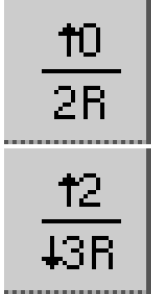
Answer:
The upper reservoir dispatched given the following slots:
• Inflow (there is an Upstream Linkable arrow next to the slot priority), which was set as a user input (the priority is 0).
• Storage or Pool Elevation (there is no arrow next to the slot priority), which was set by Rule #2 (the priority is 2R).
Therefore, the upper reservoir must have solved for its Outflow at priority 2; Rule #2 must have been the last successful rule at the time the upper reservoir got enough information to solve.
The lower reservoir dispatched given the following slots:
• Inflow (there is an Upstream Linkable arrow next to the slot priority), which was set as a result of the upper reservoir’s dispatch at priority 2 (the priority is 2).
• Outflow (there is a Downstream Linkable arrow next to the slot priority), which was set by Rule #3 (the priority is 3R).
So, the lower reservoir must have solved for its Storage and Pool Elevation at priority 2 or 3. We cannot be sure of the priority of Storage and Pool Elevation from the information given. If Rule #2 made its assignment first, the last successful rule to fire before the lower reservoir’s dispatch must have been Rule #3; Storage and Pool Elevation would have a priority of 3. If, however, Rule #3 made its assignment first, the last successful rule to fire before the lower reservoir’s dispatch must have been Rule #2 (which would cause the lower reservoir’s Inflow to be known); Storage and Pool Elevation would have a priority of 2.
The directional arrows may be turned on or off by selecting or clearing the Show Slot Link Directions checkbox under the dialog View menu. In the same menu, you can enable or disable the automatic updating that occurs every timestep by selecting or clearing the Update After Every Timestep checkbox. Turning off the updating may save some time if you are running a long model with the Model Run Analysis dialog open.
Dispatch Behavior Details Dialog
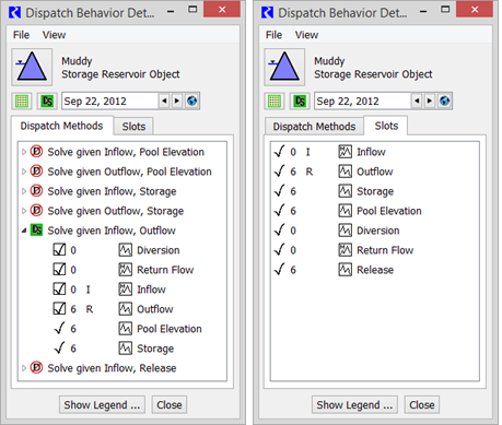
The Dispatch Behavior Details dialog is similar to the one in the Model Run Analysis—Simulation dialog, but contains additional information. In both the Dispatch Methods view and the Slots view, the priorities and flag status of slots is displayed as well as their known/unknown status. The slot priorities and flags, along with knowledge about how objects select a dispatch method, allow the user to understand why each object solved the way it did.
In using the Dispatch Behavior Details dialog to determine why an object solved using a particular dispatch method, it is important to recognize that the display only shows the post-dispatch information. This is different from the information before the dispatch. After the dispatch, all slots which are solved for have the priority equal to the controller priority at the time of the dispatch.
If, however, the dispatch of an object fails due to a priority conflict, the Dispatch Behavior Details dialog will still show the original priorities and R flags of the slots. This can be helpful in debugging an aborted run. Figure 2.5 illustrates.
Figure 2.5
Comparing Transient and Final Information
An important difference between the diagnostics messages and the Model Run Analysis—Rulebased Simulation dialog is their handling of transient information. Diagnostics messages are generated continuously throughout the run, while the Model Run Analysis—Rulebased Simulation dialog updates its information at the end of each timestep. Diagnostics messages provide a trace of the run execution, including all intermediate states within a timestep. The Model Run Analysis—Rulebased Simulation dialog, however, provides a snapshot of the most recent execution details from the perspective of the end of the timestep. Any intermediate states of dispatching, slot values, and priorities which existed before the solution was finalized for the timestep are unavailable.
Governing Rules
In addition to displaying dispatch information and slot priorities, the Model Run Analysis—Rulebased Simulation dialog allows you to trace the effects of rules across a model. When a rule sets a value which triggers a dispatch, the dispatch may calculate a new value which will propagate to another object. This object will then redispatch, possibly setting a value which will propagate to yet another object. In this fashion, the effect of a rule may propagate well beyond the object on which it sets a value. Ultimately, it is the highest-priority, successfully executed rules that determine the model solution. The priority of these rules is reflected in the governing slots for each object’s last dispatch. The priority of the governing slots identifies the governing rules.
Governing Rules The governing rules for an object are the rules whose priorities are responsible for the values on the object’s governing slots. |
In the lower-right corner of the Model Run Analysis—Rulebased Simulation dialog, an area called Frame Cells With Effects: allows the user to show which rules govern the solution. For example, changing the Option menu from None to Equal To (==) and entering 1, puts a box around all object and timestep pairs that are governed by this priority.

The Effects frame also has a checkbox for enabling “R” Effects Only. As the name indicates, selecting this checkbox will only mark the cells of the proper priorities, which were also set directly by a rule.
Rule Effects Details Dialog
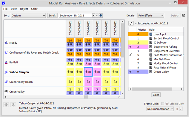
The same ability to mark cells which meet priority criteria is also available in the Rule Effects Details dialog. This dialog also displays the names of all rules and whether each rule succeeded at the selected cell’s object and time. Finally, this dialog allows you to color-code governing rules for a strong graphical way of tracking their effects across a model. A sample is shown on the following page.
Note: This dialog is always docked within the Model Run Analysis—Rulebased Simulation dialog.
• The Rule Effects dialog is shown by Selecting View, then List Rules / Set Rule Colors from the Model Run Analysis—Rulebased Simulation dialog or, if a Details dialog is currently docked in that dialog, selecting Rule Effects for the details type.
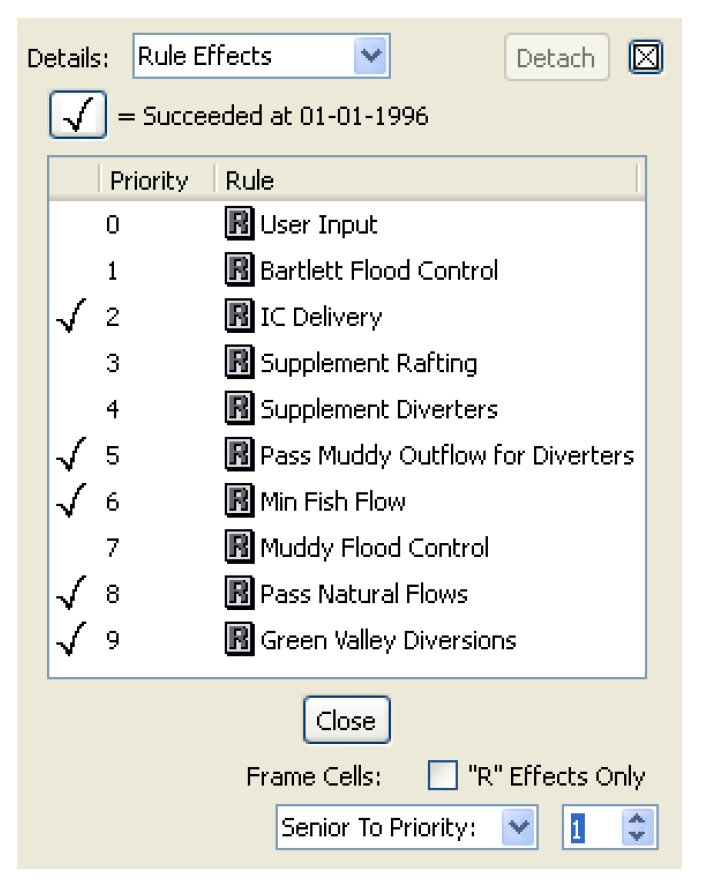
The same commands in the Model Run Analysis—Rulebased Simulation dialog’s Effects box are in the bottom of the Rule Effects dialog. Making a selection in this dialog automatically has effect in the other dialog. Governing rules may be selected by name rather than priority number by selecting their name in the top of the dialog. The check marks to the left of each rule indicate whether or not the rule fired successfully on the timestep reported in the middle of the dialog. Selecting each timestep’s cell in the Model Run Analysis—Rulebased Simulation dialog lets you see the successful rule firings for that timestep.
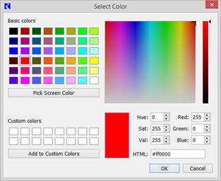
To assign colors to governing rules, select a rule in the Rule Effects dialog and select Color, then Edit. This brings up a color selector for assigning a color to portions of any cells in which this is a governing rule.
Rule Colors can be enabled or disabled by selecting View, then Show Rule Color.
Revised: 08/02/2021