
Objects on the Workspace
The workspace displays the objects representing features in the basin. The object icons are a convenient way to visualize the physical layout of a modeled system. These objects also contain the data and the physical process algorithms that drive the simulation. This section describes how to manage objects on the workspace.
Object Palette
Objects are added to the workspace using the object palette. The Palette contains all of the available object types used to represent features of a river basin. It is the source from which objects are instantiated on the workspace. To place objects on the workspace, drag them off the object palette and place them in the desired location on the workspace. You can access the Object Palette as follows:
• Select the Object Palette button on the main toolbar. 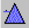
• Select Workspace, then Objects, then Object Palette from the menu bar.
• Right-click the workspace. This will bring up a small window with the option to Add Object. Selecting the Add Object option opens a list of all objects. Selecting the desired object will place it on the workspace.

An object is created by selecting its icon and dragging it off the Palette onto the workspace. At the time an object is created, the first timestep and timestep size in Series Slots are matched to the Run Control run time settings. The slots show display attributes (Units, Scale, Precision, and Format); see Unit Schemes for details. Default user methods are also selected for new objects. Slots associated with the selected controller and Methods are allocated in memory. See Object Types in Objects and Methods for details on each type of object.
Opening an Object
To open an object to see its slots, method selections, accounts, and description:
• Double-click the icon on the workspace, or
• Double-click the object icon in the workspace object list.
This displays the Object Viewer. See Object Viewer and Open Object Dialogs for details.
Selecting Objects
Objects can be selected for various reasons such as moving them, deleting them, or adding them to a subbasin. Once an object or group of objects has been selected, it will be highlighted both on the workspace and in the dockable list window.
The following are ways to select an object on the workspace:
• Select the object’s icon.
• Draw a rectangle around the object. To select multiple objects at the same time, draw a rectangle around a group of objects.
• Control-clicking an object toggles the object in and out of the selection
• Shift-clicking and dragging a rectangle adds objects to the selection.
• Right-clicking an object (to show its context menu) also adds the object to the selection.
• Selecting the object in the object list. Control and Shift-clicking allow selection of multiple objects in the list window.
Deleting Objects From the Workspace
Deleting objects from the workspace by selecting one or more objects, then right-clicking one of them. Select Delete Object from the menu. A confirmation dialog appears to inform that the selected objects will be removed from workspace.
This deletion can also be accomplished by selecting one or more objects and pushing the Delete key or by selecting the objects and then from the main menu select Workspace, then Objects, then Delete Selected Object(s). In both cases, confirmation is still required.
Moving Objects on the Workspace
An object can be moved by selecting it and holding down the button while dragging the object to the desired location. This will readjust the links to the object as well. A set of selected objects can be moved while maintaining their relative positions. The selected objects remain visible on the workspace during the move. Moving objects will change the Display Coordinates on the Geospatial view but will not change the Actual Coordinates; see Object Coordinates for details.
Enabling and Disabling Dispatching
Objects on the workspace are shown grey when dispatching is disabled. Tooltips indicate the state as well. A sample is shown in Figure 1.26. In this state, the objects will not dispatch, but they will still execute beginning of run checks. Enable or disable dispatching by right-clicking the selected objects and selecting Enable/Disable Dispatching. See Disabling Dispatching in Debugging and Analysis for details.
Figure 1.26

Object Clusters
Object Clusters allow you to group together simulation objects on the workspace and show only a single icon.
Figure 1.27

Clusters have the following properties:
• Clusters are display-only; they have no effect on the model solution.
• Clusters are supported on the Simulation and Geospatial Views. They are not supported in the Accounting View.
• Clusters can contain any simulation objects which appear on the workspace, except other clusters.
• A simulation object can be a member of only one cluster.
• Adding a simulation object to a cluster does not effect the object's locations within any of the workspace views.
• For any cluster, you can switch between the following display options:
– Displaying the cluster icon with either the default orange dot or the icon for any member object. See image to the right.
– Displaying the individual member objects' icons with a black dot in the bottom-right area of the icon indicating it is part of a cluster.
• When the cluster icon is shown, links between objects in the cluster and objects outside of the cluster are drawn to the cluster icon.

• Cluster settings are independent between the Simulation and Geospatial view. For example, a cluster can be shown with a cluster icon in the Geospatial View and with individual member object icons in the Simulation View.
• An item for each cluster appears as a top-level item in the Simulation Object List. Each cluster item has a tree view showing each of its member simulation objects. A particular object can appear twice in the list.
Note: In Figure 1.28, “BigRes” (a level power reservoir) appears twice.
• On the workspace, hover over the cluster to see a tooltip with a list of the member objects.
Figure 1.28

Following is more information on how to create and use Clusters.
Creating a Cluster
To create a new cluster, select one or more simulation object icons on the Simulation or Geospatial workspace and do one of the following:
• Right-click one of those selected object icons and select Add to Object Cluster, then New menu.
• Use the Workspace, then Object Clusters, then Add to Object Cluster, then New menu on the workspace.
If any of the selected simulation objects are already in a cluster, the Add to Object Cluster context operation is instead presented as Move to Object Cluster. This operation is used to move objects from one cluster to another.
Note: An object can be in only one cluster.
Operations on a Cluster
In general, to modify a cluster you can either right-click the cluster on the workspace, right-click the cluster in the Object List, or select the cluster and use the Workspace, then Object Cluster menu.
Following explains the various options, depending on the selection and the menu chosen, as follows:
• Show as Individual Object Icons. Shows the member object icons and hide the cluster icon. Each object will show a black dot in the lower right indicating it is part of a cluster.
• Show as Single Icon or Show as Object Cluster. Shows the cluster icon and hides the member object icons.
• Open Member Object. Shows a menu of the member objects. Selecting one of those objects opens that object’s Open Object Dialog.
• Set Icon. Select the icon to use in the center of the cluster's icon. A cluster's context menu's Set Icon menu presents each of the member objects’ icon, as shown in Figure 1.29. Select one of these items to set the small icon in the middle of the cluster icon.
Figure 1.29

• Delete Cluster / Delete Selected Cluster. Delete the cluster, showing the individual members' icons. The member objects are displayed in their original positions with their icons displayed. You must confirm this operation.
• Remove (Selected Objects) From Cluster. Remove the selected member objects from their containing cluster. Their icons will be shown on the workspace as usual.
• Add Selected Objects to Cluster. From the Workspace, then Object Cluster menu, you can choose this option to add the selected objects to the specified cluster.
Opening a Cluster
To see a list of the objects in a cluster, use one of the following methods to open the cluster.
• Double-click a cluster's Workspace icon.
• Double-click a cluster's Simulation Object List item.
• Select Open Cluster in a cluster's workspace icon context menu.
• Select Open in a cluster's Workspace Object List item context menu.

The Open Cluster Dialog shows the member objects in a list. Sort by object type or object name by selecting the column header. From this dialog, you can do the following:
• Rename the cluster using the Name field.
• Use the Objects menu to open the selected object.
• Use the Objects menu to add simulation objects to the cluster using the object selector dialog.
• Use the Objects menu to remove selected member objects from the cluster.
• Use the Icon menu to set the cluster's icon to the default cluster icon 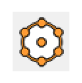 or a cluster icon containing a small version of the selected object.
or a cluster icon containing a small version of the selected object.• Open any of the member objects by double-clicking them.
Most of these operations are also available by right-clicking an object/cluster in the Simulation Object List.
Importing and Exporting Objects
Objects can be exported to a file and then imported into the same or another model. Exporting one or more objects includes exporting slot data, method selections and optionally links, accounts and supplies. Objects can be imported and exported to and from the workspace as follows.
Export
To export, first select, one or more objects. Then select Workspace, then Objects, then Export Object from the main workspace. The user is then presented with the Export RiverWare Simulation Object File dialog, which is used to specify how the objects should be exported and to which file the objects should be written. Figure 1.30 illustrates.
Figure 1.30

The following options are available for exporting depending on the model and possibly the selected objects’ components.
• Links. Specify whether to write Links between slots.
• Attributes. Object attributes defined on the Attributes Manager and selected on the object’s Attributes tab can be optionally exported.
• Accounts. In an accounting model, select the type of accounts to export: Storage, Diversion, Instream Flow, and/or Passthrough accounts.
• Supplies. In an accounting model, specify whether supplies should be exported.
• Text Notes. Specify whether to write Associated Text Notes. See Notes on Series Slots for details on notes.
As noted on the dialog, when the objects are part of an Object Clusters, both the cluster configuration and member objects are exported. When you import, you can choose whether to import objects and configuration or just the cluster configuration. See Import for details.
When exporting objects and links, only those links between exported objects will be written. Similarly, only those supplies between exported accounts will be written. In addition, the following are not exported:
• Subbasin membership of exported objects
• Computational subbasins
• Workspace display groups including Link, Object, Supply, and Account Groups
• Accounting exchanges including paybacks
• Accounting user defined object level methods - These may be exported separately from the RPL set.
Note: Method selection is exported on objects. It is important to export/import the object level accounting methods first as imported objects cannot reference methods that do not exist in the model
• For snapshots data objects, the reference to the original slot. When plotting slots and their snapshots from the output manager, the output manager cannot automatically plot a slot and its imported snapshots.
Import
To import, use the Workspace, then Objects, then Import Object menu from the RiverWare workspace. On import, the objects will have the same name as the original object unless an object by the same name already exists in the model. In this case, an integer is added to the object’s name. The following options are available on import.
• Specify whether text notes should be imported, as follows. See Notes on Series Slots for details on text notes.
– Don’t import notes
– Import but Don’t overwrite existing notes
– Import and Allow overwrite of existing notes
• Specify a selection for Object Cluster Import, as follows:
– Import member objects and cluster configuration
– Import cluster configuration only
• Specify a selection for Import Location, as follows:
– Use exported coordinates. On import, the objects will be placed at the same coordinates as the objects in the model from which they were exported in both the simulation, accounting, and geospatial views. If the workspace is too small to accommodate these new objects, the workspace will grow to exactly fit the imported objects (including a small border).
– Near object. Choose a reference object and the imported objects will be put to the right of that object. Technically, the lower left corner of the bounding box around the imported objects is placed just to the right of the reference object. This is true for all three canvas views. This option is particularly useful when importing objects from a model of one basin to a model of a completely different basin, with vastly different coordinates.
• Specify whether to Import Object Attributes.

Imported objects are automatically selected (highlighted). Typically the user will then move all of the imported objects immediately to the desired location by dragging them on the workspace. This is especially true if they are on top of other objects. While the objects are still selected, it may be useful to create a subbasin of these objects so they may be easily selected later. See Creating New Subbasins for instructions on creating a subbasin from the selected objects.
Objects are similar to model files; they can only be imported in models that have the same or higher version number, e.g. an object exported from a RiverWare 5.0 model can only be imported into RiverWare 5.0, 5.1, etc.
When an object or supply is imported and the name already exists in the model, the newly imported objects will be renamed by adding a number to the end of the name. The supplies will then be renamed using the default supply naming convention, “Object# Account to Object# Account”. A warning message is posted. If this new name is not available, because of multiple supplies between the same two accounts, the word “DUPL” is added to the end of the supply name to make it unique. These supply names can be changed from the account configuration. Accounts should not need to be renamed as account names are not unique only the object names are.
Export and Import Tips
There are a number of scenarios in which import/export of objects could be useful. One such example is when a team of modelers wish to break up a model and have various people work on different components. Following are some tips for this process.
Each team member would take the full model and then pare it down to the desired objects, do the modeling work and then recombine the pieces into one model. To pare down a model, it is typically better to delete unused objects than to export and import the desired objects into another model. By deleting objects, the Run Control parameters--run range, timestep length, controller, settings--are preserved. Also, the output devices, DMIs, object level accounting methods are then available in the pared down model.
To then recombine the model with the original, it is best to delete the objects from the original model and then import the new objects from the pared down version(s). This prevents naming conflicts and having to rename newly imported objects.
Revised: 08/02/2021