
Initialization for Routing Methods
In routing reaches, the user must input enough data before the start of the run (presimulation) to allow the reaches to solve for the Outflow at the first (and possibly subsequent) timestep. The necessary slots and number of presimulation values required to ensure solution of the entire system at the start timestep depends on the number, type, linkages, method selection and parameterization of objects in the system.
In most circumstances, the modeler identifies the presimulation data requirements through knowledge of the system or trial and error. These data are then specified (manually or via input DMIs) to provide the model with required and reasonable data. This section describes an approach to automatically initializing flow slots at presimulation timesteps so routing can simulate successfully at the first computational timestep.
Slots Requiring Presimulation Values
The following section describes the slots used in USACE‑SWD models requiring presimulation data.
1. Outflow from each reservoir to initialize inflows to downstream routing reaches.
Note: Reservoirs never dispatch before the start of the simulation and as a result, reservoirs need neither Inflow nor Hydrologic Inflows, before the start of the run. Of course, reservoirs still require 1 initial value for pool elevation or storage. Also, certain methods require a single value for the initial timestep. For example, the tailwater methods require an initial Tailwater Elevation. These single initial values will still need to be input by the user.
2. Seepage from each reservoir, when in use and linked. Typically, the reservoir Seepage slot is linked to the outflow Control Point’s Local Inflow slot. When non-zero, Seepage is typically a small value. But the Seepage needs to be initialized to provide reasonable flows downstream on the first timestep.
3. Flow into the upstream-most non-reservoir object of each tributary, typically a control point inflow or possibly a reach inflow. In the case of many models, these are all control point objects (often called Dam sites).
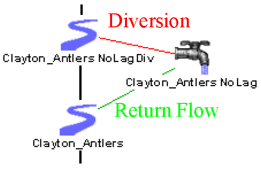
In the USACE‑SWD models, secondary flow paths have been created to allow Low-flow Releases to be diverted around the routing reaches as shown in Figure 2.4. Because this modeling approach requires a No Routing reach and a water user, additional presimulation values are required to solve these two reaches at the first timestep. See Low-flow Releases for details.
4. Diversion on reaches diverting to water users. In addition, any direct-from-reach diversions will also need the Diversion slot initialized.
5. Return Flow on reaches when linked to water users.
Note: Although Diversion and Return Flow are not typically required to solve a reach, if these two slots are linked but unknown, the reach will dispatch but not solve.
In the above screenshot, the two reaches are linked to the water user (Reach.Diversion to Water User.Diversion, Reach.Return Flow to Water User.Return Flow). As a result, it is only necessary to set one side of the link and it makes no difference which side is set. Therefore, it would be identical to initialize the Water User’s Diversion and Return Flow slots.
6. Local Inflow on reaches, when instantiated.
Figure 2.4 Linking structure for secondary flow paths
Presimulation Values
Currently in USACE‑SWD models, all presimulation values are set to zero. On the Local Inflow, Diversion, and Return Flow slots, this value may be reasonable. But zero reservoir outflow does not seem reasonable as this value will propagate downstream. Therefore, the above slots can be initialized using one of the following methods:
1. Assign zero to all presimulation timesteps.
2. Assign the user-input value at the initial timestep to all presimulation timesteps on that slot.
Required Number of Presimulation Timesteps
For each object, the method determines the number of required presimulation values by visiting each downstream reach object and looking at the routing characteristics. The search is stopped when a reservoir or other object that does not dispatch before the first timestep is met or the downstream-most point in the basin is found. Objects that do not dispatch before the timestep are: Reservoir (all types), Pipeline, Inline Pump and Bifurcation. The upstream to downstream search will stop at any of these points.
Note: Even though the Gage does not dispatch before the start of the timestep, its inflow and outflow are linked, allowing any upstream values to propagate downstream.
Reservoirs of all types, Pipelines, Inline Pumps and Bifurcations will not calculate a mass balance for timesteps before the begin of the run, so reaches downstream of these points must be initialized as if they were at the top of their basins. For example, flows above a reservoir will not affect the outflows specified for the reservoir because the reservoir cannot solve prior to the start timestep.
To ensure that this algorithm produces the same results for model files without the initialization method, every object is checked to see that it is a member in a subbasin with an initialization method. If the object is not a member, the number of lags calculated will be zero, and the results of the first dispatch timestep will be the same as without these methods selected.
The number of required presimulation values will be determined as follows:
• Visit each reach in the flow path and sum the number of lag coefficients. For each object, the required number of presimulation timesteps is calculated using Equation 2.1.
(2.1) 
Note: This approach assumes you can determine the maximum number of coefficients a priori. Therefore, it only works for the No Routing, Step Response, Variable Step Response, Impulse Response, Time Lag, or Variable Time Lag methods.
• When diagnostics are turned on, Reaches and Aggregate reaches report the total number of downstream timesteps required in order to solve the most downstream object at the first timestep. Aggregate Reaches, like other objects, report the total number of timesteps required, but because they contain reaches, the contained reaches also report the number of timesteps required.
Methods
See Initialize Flow Slots for Routing in Objects and Methods for details.
Using Initialization Methods
To apply the initialization functionality to an existing USACE‑SWD model, the following steps are required.
1. Create a subbasin.
2. Define initial values as necessary.
3. Disable existing initialization rules.
This section will identify and walk through these steps.
Create an Initialization Subbasin
The Initialization methods reside on a Computational Subbasin. While several computational subbasins exist in USACE‑SWD models, it is recommended that a new subbasin be created to ensure that all simulation objects be considered for initialization; not just those listed in an existing subbasin.
• Open the Workspace, then Edit Subbasins dialog.
• Select the Subbasin, then Append Typed Subbasin, then Computational Subbasin.
• Select the new subbasin to rename it, then select Subbasin, then Invoke Member Selector.
• Use the Selector to select all simulation objects (excluding data objects) as members of the subbasin.
• Close the Subbasin Manager dialog and return to the workspace, select Workspace, then Open Computational Subbasin, then <Name of the New Subbasin>. Shift to the Methods tab and select the desired initialization method from the Initialize Flow Slots for Routing category. For simplest initialization, select Backcast Zeros. Otherwise, select Backcast Initial Value.
If further flexibility is required, the user may create separate subbasins to initialize objects differently. For example, choose to specify all reservoirs as part of a Computational Subbasin that Backcasts the Initial Value. All the other objects should be part of a Computational Subbasin that would Backcast Zeros. This approach is possible because all of the objects in the model should be in a subbasin to find the correct downstream lag, they don’t necessarily have to be in the same subbasin.
Define Initial Values as Necessary
In past USACE‑SWD models, slots requiring initialization values were set with rules and/or were set manually. If desired, these user-input values may now be removed, resulting in the model relying more fully on the Initialization methods. Remember that these user input values or any extra values do not interfere with proper execution of the Initialization methods, but may be unnecessary. While there are several means to accomplish removing the initial values, during development and testing CADSWES staff found the following method to be relatively efficient.
1. Create a new SCT and add all existing slots to it.
2. Under Config, then General, extend the display period by setting the Pre-Run Timesteps value to a high number.
3. Scan through the slots focusing at or near the Initial Timestep for those shaded as User Input (gray). When a slot is found with user input, remove those values as appropriate. If you have selected Backcast Initial Values, make sure to leave one input value on the initial timestep.
Remember that certain slots require user input at the Initial Timestep, such as Reservoir Storage or Pool Elevation.
Deactivate or Remove Initialization Rules
If previous initialization efforts included usage of rules to initialize diversions, return flows or local inflows, these rules should be removed or deactivated. If the chosen method is Backcast Zeros, the model should run.
Other Suggested Changes
Change no-lag reaches to use the No Local Inflow, Solve Outflow method to avoid requiring the Local Inflow to have a initial value. See No Local Inflow, Solve Outflow in Objects and Methods for details.
Diagnostics are available for the initialization methods under the Dispatch Management, SimObj category. Make sure to select the computational subbasin in the object filtering section.
Revised: 08/02/2021