
Reservoir Objects
When selecting a reservoir object to represent a reservoir/dam that has power production capabilities, it is best to select a power reservoir object even if the model will not be used for modeling power initially. It is easy to enable and disable power modeling on a power reservoir object but it is not as easy to change from a storage reservoir to a power reservoir after the model has already been completed.
Required Inputs
Input the relationship between pool elevation and storage in the Elevation Volume Table slot. Also, for every reservoir, an initial Pool Elevation or Storage is required.
On storage reservoirs, input the pool elevation versus release information in the Max Release slot (For level power reservoirs, similar data will be entered based on the selected power method as described in the next section).
Power Methods
For level power reservoirs, the user must select a method in the Power Calculation category regardless of whether or not the object will be used for power calculation. If the object will not initially be used to compute power, select the No Power Turbine Flow method. When this method is selected the Max Flow Through Turbines slot will be added and should be populated with the relationship between pool elevation and the maximum outflow through the turbines. However, no power calculations will take place. If the user does wish to model power, he/she should select the appropriate power calculation method. At this stage any of the methods can be used, but if releases are to be made using the HydropowerRelease function (see Hydropower), then the Peak Power Equation with Off Peak Spill method should be selected. See Peak Power Equation with Off Peak Spill in Objects and Methods for details on the required data.
Tailwater Methods
When a power method is selected, a tailwater method must also be selected. See Tailwater in Objects and Methods for details on the available methods.
When setting up the tailwater method, there are some important aspects to remember. The Tailwater Base Value is a series slot that is used to link to a downstream reservoir’s Pool Elevation. If the Tailwater Base Value is not linked to a downstream reservoir, it is best to leave NaNs in the Tailwater Base Value and have the Tailwater Table include all of the data necessary to calculate the correct tailwater.
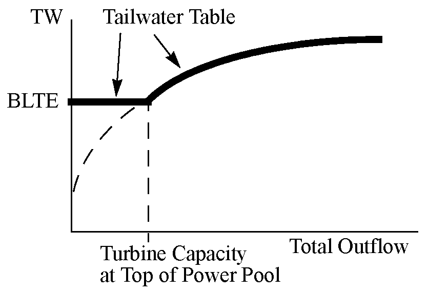
This section describes how SUPER tailwater data can be input into the Tailwater Table to mimic SUPER’s functionality. In SUPER, there is a variable called the Block Loading Tailwater Elevation (BLTE). This is defined as the tailwater that results when releasing Turbine Capacity with the reservoir at the top of the power pool with no other releases. In this description, this is called the “Turbine Capacity at Top of Power Pool.”
The Tailwater Table can be input such that the look up flow will result in the correct tailwater elevation. The table will be as follows: If the flow is less than or equal to the Turbine Capacity at Top of Power Pool, then the tailwater is a constant value equal to the BLTE. If the flow is greater than the turbine capacity at top of power pool, then the value is from the right portion of the curve. See Figure 2.1. Based on sample input data, only the right portion of the curve is currently input into SUPER. This method will allow the USACE‑SWD to first input the table to mimic the SUPER methodology but in the future, the full table can be input.
Figure 2.1 Tailwater table diagram
Spill Methods and Required Data
In RiverWare, a spill is a portion of the outflow that does not go through the turbines (on a power reservoir) or through the main release works (on a storage reservoir). Spills can be controlled (Regulated Spill and Bypass) or uncontrolled (Unregulated Spill).
Spill Calculation Category
The spill calculation category is used to model various spillway structures and configurations. Select a spill method only if the model will differentiate between spillway outflow and outflow through the release gates. If a single curve is used to represent total reservoir outflow as a function of pool elevation, then no spill method is necessary. On a storage reservoir the flow vs. pool elevation data is held in the Max Release slot while on power reservoirs it is held in the power method specific slot. If uncontrolled spillways or additional controlled release structures need to be modeled, select the appropriate spill method. If a spill method is selected, enter flow vs. pool elevation data for the various release and spill structures modeled. See Spill in Objects and Methods for details on the spill methods.
If a spill method is selected, input the pool elevation vs. spill information on the appropriate slots. For USACE‑SWD applications, the “Drift” slots are not used and can remain empty.
Spillway and Release Modeling
Previously, the USACE‑SWD used a single relationship to define the maximum outflow as a function of pool elevation. This relationship is called the free flow rating curve. The free flow rating curve includes outflow through the turbines, regulated spillways, and unregulated spillways. Normally, the proper spill method would be selected to model each of these outflow structures separately. The data in the free flow rating curve would then need to be disaggregated for each outflow structure modeled. Originally, the USACE‑SWD decided not to model each outflow structure separately and wanted to leave the free flow rating curve intact (as opposed to disaggregating the information). Therefore, they did not select a spill method and instead input the free flow rating curve (maximum total outflow vs. pool elevation) in the Max Release slot on storage reservoirs and in the Max Flow Through Turbines slot on power reservoirs. RiverWare will solve normally when configured in this fashion. Instead of using spillways and regulated spill structures, all outflow is sent through the Release slot (on storage reservoirs) or the Turbine Release slot (on power reservoirs). While this will not affect the reservoir calculations, it is misleading because the Turbine Release and Release slots will show outflow for both the release and spill structures. This would not work if the reservoir is being used to compute power. In that case, a spill method should be selected. The sum of the turbine release capacity and spill capacities should equal the free flow rating curve.
Order of Spillway and Release Structures Used in RiverWare
If more than one spillway or release structure is being modeled on a given reservoir, RiverWare sends the reservoir outflow through these structures in a specific order. If there is an uncontrolled spillway, the spill over that structure is computed based on the average pool elevation over the timestep. Any remaining outflow is then sent through the turbines, if it is a power reservoir, or through the Release slot if it is a storage reservoir (the maximum release information is held in the Max Release slot). If there is any remaining outflow, it is sent through the Regulated Spill slot or the Bypass spill slot depending on the spill method selected. In general, RiverWare assumes that all outflow should go through the turbines (or the Release slot on storage reservoirs) and any excess is sent through the regulated spill structures.
Inflows
There are many slots on the reservoirs that can represent sources and sinks to the mass balance. This section describes the recommended structure for the inflows to the reservoir.
Reservoir Inflow and Mass Balance Data
The Inflow slot represents the inflow to the reservoir from upstream (routed flows from upstream, not uncontrolled area flows). Therefore, the Inflow slot on all reservoirs should be linked to the Outflow slot of the upstream object unless the reservoir is a headwater reservoir. If it is a headwater reservoir, a flow rate of zero should be input for all timesteps (including values through the last dispatch timestep) in the Inflow slot (the reservoir will still receive inflow from the Hydrologic Inflow Forecast slot).
Since the inflow to each reservoir will be known (either propagated from an upstream object or input to zero), one other piece of data must be input for each timestep to allow the reservoir to mass balance. An initial value for either storage or pool elevation must be input and then values must be input at each timestep for either pool elevation, storage or outflow. For testing purposes, and to ensure proper mass balancing, various combinations of inflow, outflow, storage and pool elevations can be input and evaluated.
Forecast Inflow—Uncontrolled Area Flow
The reservoir objects (and control points) are used to bring uncontrolled area flows into the system. The USACE‑SWD data for uncontrolled area flows is the cumulative, uncontrolled area flow from the upstream reservoir to the control point, adjusted for routing. As a result, it cannot be input directly into the Local Inflow slot or the flows would be multiply counted. Also, the uncontrolled flows must be forecasted to provide an estimate throughout the forecast period. Specific methods must be selected to deal with these two unique features. See Forecasting Incremental Local Inflows From Cumulative Flows for details.
Seepage
Seepage through the face of the dam is modeled by selecting the Input Seepage of Single Seepage Value method in the Seepage category. These methods allows the user to input a timeseries of seepage values or a constant value. The Reservoir.Seepage slot should then be linked to the downstream object’s Local Inflow slot. Figure 2.2 shows the correct linking structure.
Figure 2.2 Linking seepage

Other Possible User Methods
There are several other user method categories available on the reservoir that are not discussed in this document. Decide what additional physical processes need to be modeled (if any) and then select the appropriate methods and input the appropriate data. Possibilities include evaporation and precipitation, or bank storage. See User Methods in Objects and Methods for details on the methods and associated slots.
Revised: 01/10/2022