
Solution / Dispatching
Topics
Beginning of Water Quality Run
The following functionality is executed one time at the beginning of the run. It is called from within beginning of run behavior on the Reservoir object.
Using Layered Methods to Model Temperature
1. Check for initial epilimnion and hypolimnion temperatures. If not input, then flag an error and exit
2. Check Specific Heat slot for input. If not input, then set to standard value of 4.186 KJ/g C.
3. Check Reservoir Geometry Coefficients for data. If not input, then execute utility method cubicFit.
4. Check Release Elevation, Reservoir Length, Thickness of Epilimnion, and Thickness of Metalimnion for input. If not input, then flag an error and exit.
5. If the Withdrawal Zone Coefficient is not valid, set it to 1.0.
6. Check for Air Temperature, Dewpoint Temperature, and Solar Radiation data. If data is incomplete, then flag error and exit.
7. If Wind Velocity data is incomplete, set is to zero
8. If Thermo Diffusion Coefficient Adjust data is incomplete, then fill values to 1.0.
9. If Diversion, Return Flow, or Inflow are not linked and not valid, set corresponding temperatures to zero.
10. For a Slope Power Reservoir, if Inflow2 is not linked and not valid, set corresponding temperatures to zero.
Using Layered Methods to Model Salinity
1. Check for initial epilimnion and hypolimnion salt concentrations. If not valid, then flag an error and exit.
2. If Diversion, Return Flow, or Inflow are not linked and not valid, set corresponding salt concentrations to zero.
3. For a Slope Power Reservoir, if Inflow2 is not linked and not valid, set corresponding salt mass to zero.
Using Layered Methods to Model Dissolved Oxygen
1. check for initial epilimnion and hypolimnion detritus, dissolved organics, ammonia, and dissolved oxygen concentrations. If not input, then flag and error.
2. If Diversion, Return Flow, or Inflow are not linked and not valid, set corresponding detritus, dissolved organics, ammonia, and dissolved oxygen concentrations to zero.
3. Check for data in following slots: Detritus Parameters, Dissolved Organics Parameters, Ammonia Parameters, SOD Parameters, Photosynthesis Parameters, Respiration Parameters. If any data is missing, flag error and exit.
4. For a Slope Power Reservoir, if Inflow2 is not linked and not valid, set Inflow2 detritus, dissolved organics, ammonia, and dissolved oxygen concentrations to zero.
Using Well Mixed Salt Method
1. Check for initial Reservoir Salt Concentration, initial Bank Storage Salt Concentration, and Dead Storage. If not input, then set to zero.
2. If Hydrologic Inflow Salt Concentration, Return Flow Salt Mass, or Diversion Salt Concentration are not linked and not input, then set to zero.
Using Segmented 2 Layer Method
1. Check the Agg Series Slots and Table slots to ensure they contain the number of rows or columns which correspond to the number of segments.
2. Check for initial Epilimnion Salt Concentration by Segment, Hypolimnion Salt Concentration by Segment, and initial Bank Storage Salt Concentration. If not input, then set to zero.
3. If Hydrologic Inflow Salt Concentration, Return Flow Salt Mass, or Diversion Salt Concentration are not linked and not input, then set to zero.
4. Check the Segment Parameters Table to ensure all proportions sum to 1.
5. Calculate initial values for Epilimnion Volume by Segment, Hypolimnion Volume by Segment, Bank Storage by Segment and Reservoir Salt Mass.
Modeling TDG
1. Check for valid values in the slots: Tailwater Bottom Elevation, TDG c1, TDG Entrainment b1, TDG Entrainment b3, TDG Spill b2, TDG Spill and Turbine Release Limits.
2. If the Opt Outflow TDG Tailwater Depth is selected, make sure a valid Tailwater method is selected. See Opt Outflow TDG Tailwater Depth for details.
Dispatch Slots
Dispatch slots appear in the dispatch conditions of the Dispatch Methods, link to another object, or both. Thus, the existence of a value in these slots determines when the object dispatches and which Dispatch Method is executed.
Note: Specific slots depend on the selected constituents.
Layered Methods Dispatch Slots
• Canal Flow Ammonia Conc | • Outflow Dissolved Oxygen Mass |
• Canal Flow Detritus Conc | • Outflow Heat |
• Canal Flow Dissolved Organics Conc | • Outflow Salt Mass |
• Canal Flow Dissolved Oxygen Conc | • Pump Storage Inflow Ammonia |
• Canal Flow Salt Conc | • Pump Storage Inflow Detritus |
• Canal Flow Temp | • Pump Storage Inflow Dissolved Oxygen |
• Diversion Ammonia Conc | • Pump Storage Inflow Organics |
• Diversion Detritus Conc | • Pump Storage Inflow Salt |
• Diversion Dissolved Organics Conc | • Pump Storage Inflow Temp |
• Diversion Dissolved Oxygen Conc | • Pump Storage Outflow Ammonia |
• Diversion Salt Concentration | • Pump Storage Outflow Detritus |
• Diversion Temp | • Pump Storage Outflow Dissolved Oxygen |
• Inflow Ammonia Mass | • Pump Storage Outflow Organics |
• Inflow Detritus Mass | • Pump Storage Outflow Salt |
• Inflow Dissolved Organics Mass | • Pump Storage Outflow Temp |
• Inflow Dissolved Oxygen Mass | • Return Flow Ammonia Conc |
• Inflow Heat | • Return Flow Detritus Conc |
• Inflow Salt Mass | • Return Flow Dissolved Organics Conc |
• Outflow Ammonia Mass | • Return Flow Dissolved Oxygen Conc |
• Outflow Detritus Mass | • Return Flow Salt Conc |
• Outflow Dissolved Organics Mass | • Return Flow Temp |
Well Mixed Salt Method Dispatch Slots
• Diversion Salt Concentration
• Outflow Salt Concentration
• Hydrologic Inflow Salt Conc
• Outflow Salt Mass
• Inflow Salt Concentration
• Reservoir Salt Concentration
• Inflow Salt Mass
• Return Flow Salt Mass
Segmented 2 Layer Salt, Dispatch Slots
• Diversion Salt Concentration
• Outflow Salt Concentration
• Hydrologic Inflow Salt Conc
• Outflow Salt Mass
• Inflow Salt Concentration
• Return Flow Salt Concentration
• Inflow Salt Mass
TDG Method Dispatch Slots
• Inflow TDG Concentration
• Outflow TDG Concentration
• Spill TDG Concentration
• Delta Inflow
• Delta Outflow
• Delta Outflow TDG Concentration
• Delta Inflow TDG Concentration
Dispatch Methods
The controller for water quality currently has a dispatch method for each constituent and solution approach combination. They assume the mass balance has already solved and therefore mass balance slots are also required slots.
The following water quality dispatch methods exist on all reservoirs. In order for the method to be executed for each timestep, both the known and unknown slot lists must be satisfied. Each dispatch method represents a possible combination of constituent and solution approach choices made at the global level.
This dispatch method is available for the Layered Temp method.
Required Known Slots
• Diversion
• Outflow
• Hydrologic Inflow
• Return Flow
• Inflow
• Storage
• Inflow Heat
Required Unknown Slots
• Outflow Heat
Method Details
This dispatch method is available for the Layered Salt method.
Required Known Slots
• Diversion
• Outflow
• Hydrologic Inflow
• Return Flow
• Inflow
• Storage
• Inflow Salt Concentration
Required Unknown Slots
• Inflow Salt Mass
• Outflow Salt Mass
• Outflow Salt Concentration
Method Details
This dispatch method is available for the Layered Temp and Salt method.
Required Known Slots
• Diversion
• Inflow Salt Mass
• Hydrologic Inflow
• Outflow
• Inflow
• Return Flow
• Inflow Heat
• Storage
Required Unknown Slots
• Outflow Heat
• Outflow Salt Mass
Method Details
This method calls the following utility methods:
This dispatch method is available for the Layered Temp and DO method.
Required Known Slots
• Diversion
• Inflow Dissolved Oxygen Mass
• Hydrologic Inflow
• Inflow Heat
• Inflow
• Outflow
• Inflow Ammonia Mass
• Return Flow
• Inflow Detritus Mass
• Storage
• Inflow Dissolved Organics Mass
Required Unknown Slots
• Outflow Ammonia Mass
• Outflow Dissolved Oxygen Mass
• Outflow Detritus Mass,
• Outflow Heat
• Outflow Dissolved Organics Mass
Method Details
This method calls the following utility methods:
This dispatch method is available for the Layered Temp Salt and DO method.
Required Known Slots
• Diversion
• Inflow Dissolved Oxygen Mass
• Hydrologic Inflow
• Inflow Heat
• Inflow
• Inflow Salt Mass
• Inflow Ammonia Mass
• Outflow
• Inflow Detritus Mass
• Return Flow
• Inflow Dissolved Organics Mass
• Storage
Required Unknown Slots
• Outflow Ammonia Mass
• Outflow Dissolved Oxygen Mass
• Outflow Detritus Mass,
• Outflow Heat
• Outflow Dissolved Organics Mass
• Outflow Salt Mass
Method Details
This method calls the following utility methods:
This dispatch method is available for the Segmented 2 Layer Salt method.
Required Known Slots
• Storage
• Inflow
• Outflow
• Inflow Salt Concentration
Required Unknown Slots
• Outflow Salt Concentration
• Outflow Salt Mass
Method Details
This method calls the following utility method:
This dispatch method is available for the Well Mixed Salt method when the Weighting Factor Salt method is selected from the WQ Reservoir Routing category. It solves for Outflow Salt Concentration given Inflow Salt Concentration.
Required Known Slots
• Inflow
• Outflow
• Inflow Salt Concentration
• Storage
Required Unknown Slots
• Outflow Salt Concentration
• Reservoir Salt Concentration
Method Details
First, the massBalanceSaltInit utility function is called to set up local variables and verify that there are the necessary data (see massBalanceSaltInit). Next, the getAvgSaltConcIn function is called to determine the weighted average inflowSaltConcentration (see getAvgSaltConcIn).
If Storage is not valid or the reservoir’s previous and current storage are less than or equal to 5.0 acre-feet, set the Reservoir Salt Concentration equal to the Previous Reservoir Concentration and Outflow Salt Concentration to Inflow Salt Concentration then exit the method.
Next, calculate the local variable storSum as follows:
(14.7) 
Calculate the weightingFactor:
(14.8) 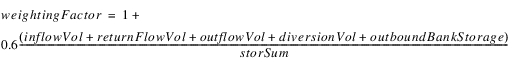
StorSum is then recalculated as follows:
(14.9) 
If storSum is equal to 0.0 then set Reservoir Salt Concentration equal to Previous Reservoir Salt Concentration. Otherwise, Reservoir Salt Concentration equals Outflow Salt Concentration.
(14.10) 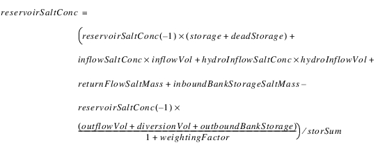
The Previous Reservoir Salt Concentration is set one time step forward to put the reservoir on the queue for the next time step. The Reservoir Outflow Salt Concentration is calculated as follows:
(14.11) 
Finally, Inflow Salt Mass, Outflow Salt Mass, Diversion Salt Mass and Hydrologic Inflow Salt Mass are set by multiplying their respective volumes and concentrations.
This dispatch method is available for the Well Mixed Salt method when the Weighting Factor Salt method is selected from the WQ Reservoir Routing category. It solves for Inflow Salt Concentration given Outflow Salt Concentration.
Required Known Slots
• Inflow
• Outflow Salt Concentration
• Outflow
• Storage
Required Unknown Slots
• Inflow Salt Concentration
• Reservoir Salt Concentration
Method Details
First, the massBalanceSaltInit utility function is called to set up local variables and verify that there are the necessary data. See massBalanceSaltInit for details.
If Storage is not valid or the reservoir’s previous and current storage are less than or equal to 5.0 Acre-feet, set the Reservoir Salt Concentration equal to the Previous Reservoir Concentration and Inflow Salt Concentration to Outflow Salt Concentration then exit the method.
Next, calculate the local variable storSum as follows:
(14.12) 
Calculate the weightingFactor:
(14.13) 
StorSum is then recalculated as follows:
(14.14) 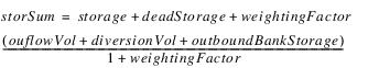
If storSum is equal to 0.0 then set Reservoir Salt Concentration equal to Previous Reservoir Salt Concentration. Otherwise, Reservoir Salt Concentration equals Outflow Salt Concentration.
(14.15) 
The Previous Reservoir Salt Concentration is set one time step forward to put the reservoir on the queue for the next time step. The Reservoir Inflow Salt Concentration is calculated as follows:
(14.16) 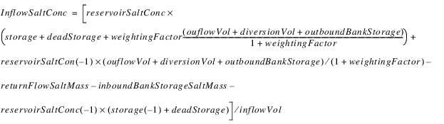
Finally, Inflow Salt Mass, Outflow Salt Mass, Diversion Salt Mass and Hydrologic Inflow Salt Mass are set by multiplying their respective volumes and concentrations.
This dispatch method is available for the Well Mixed Salt method when the Predictor-Corrector Salt method is selected from the WQ Reservoir Routing category. It solves for Outflow Salt Concentration given Inflow Salt Concentration.
Required Known Slots
• Inflow
• Outflow
• Inflow Salt Concentration
• Storage
Required Unknown Slots
• Outflow Salt Concentration
• Reservoir Salt Concentration
Method Details
First, the massBalanceSaltInit utility function is called to set up local variables and verify that there are the necessary data (see massBalanceSaltInit). Next, the getAvgSaltConcIn function is called to determine the weighted average inflowSaltConcentration (see getAvgSaltConcIn).
Next, the local variable storSum is calculated as Storage plus Dead Storage.
(14.17) 
If storSum is equal to 0.0 then set Reservoir Salt Concentration equal to ‑1.0 (the Reservoir Salt Concentration is recalculated in Equation 14.23. Otherwise, solve for the predictor (in units of salt mass):
(14.18) 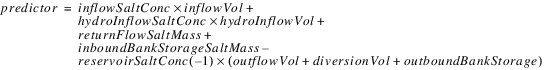
The local variable intermediateReservoirSaltConc is computed as follows:
(14.19) 
Solve for the corrector (in units of salt mass):
(14.20) 
The local variable slope is the average of the predictor and the corrector
(14.21) 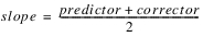
The Reservoir Salt Concentration is calculated as follows:
(14.22) 
If the calculated Reservoir Salt Concentration is negative (that is, the calculation failed to find a valid concentration because there is very little storage in the reservoir) or if storage and previous storage are less than or equal to 5.0 acre-feet, the Reservoir Salt Concentration is reset to the weighted average of the salt concentrations of the inflows.
(14.23) 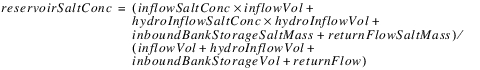
The Previous Reservoir Salt Concentration is set one time step forward to put reservoir on the queue for the next time step. Finally, the Outflow Salt Concentration is set equal to the Reservoir Salt Concentration and Inflow Salt Mass, Outflow Salt Mass, Diversion Salt Mass and Hydrologic Inflow Salt Mass are set by multiplying their respective volumes and concentrations.
This dispatch method is available for the Well Mixed Salt when the Predictor-Corrector Salt method is selected from the WQ Reservoir Routing category. It solves for Inflow Salt Concentration given Outflow Salt Concentration.
Required Known Slots
• Inflow
• Outflow Salt Concentration
• Outflow
• Storage
Required Unknown Slots
• Inflow Salt Concentration
• Reservoir Salt Concentration
Method Details
First, the massBalanceSaltInit utility function is called to set up local variables and verify that there are the necessary data. See massBalanceSaltInit.
Next, calculate the local variable storSum as Storage plus Dead Storage.
(14.24) 
If Storage is not valid or the reservoir’s previous and current storage are less than or equal to 5.0 Acre-feet, set the Reservoir Salt Concentration equal to the Previous Reservoir Concentration and Inflow Salt Concentration to Outflow Salt Concentration then exit the method.
If storSum is equal to 0.0 then set Reservoir Salt Concentration equal to Previous Reservoir Salt Concentration. Otherwise, Reservoir Salt Concentration equals Outflow Salt Concentration.
(14.25) 
The Previous Reservoir Salt Concentration is set one time step forward to put the reservoir on the queue for the next time step. If inVol equals zero then inflowSaltConc is set equal to zero, otherwise the Reservoir Inflow Salt Concentration is calculated as follows:
(14.26) 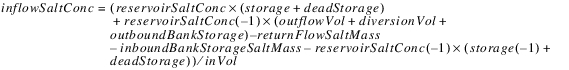
Finally, Inflow Salt Mass, Outflow Salt Mass, Diversion Salt Mass and Hydrologic Inflow Salt Mass are set by multiplying their respective volumes and concentrations.
This dispatch method computes the physical and optimization slots based on the actual slot values.
Required Known Slots
• Regulated Spill
• Tailwater Elevation
• Turbine Release
• Inflow TDG Concentration
Required Unknown Slots
• Spill TDG Concentration
• Outflow TDG Concentration
Method Details
This method executes the Outflow TDG using the Tailwater Depth method, and then executes the selected method in the Optimization Total Dissolved Gas. See Outflow TDG using Tailwater Depth for details on this method.
Utility Methods
Utility methods are methods (or subroutines, or functions) that do not belong to a user-selectable method type. For example, there is a utility method that calculates the surface area of the reservoir (see calcSurfaceArea), and one that fits a cubic function to a set of elevation - volume data (cubicFit).
Each utility method is used by one or more user-selected methods.
Note: Some of these methods set slots directly, while others return values but do not set slots explicitly.
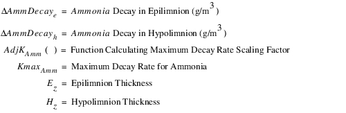
Returns a unit-less ammonia decay correction factor based on reservoir temperature and S-curve data. Inputs include an ammonia decay rate, and the corresponding temperature. Gamma is calculated with two rates and two temperatures by the function calcGamma (see calcGamma). Current layer temperature is passed in through the variable temp.
(14.27) 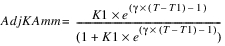
AdjKAmm should return a value between 0.0 and 1.0.
Slots With Required Known Data
• Ammonia Parameters
Returns a unit-less detritus decay correction factor based on reservoir temperature and S-curve data. Inputs include a detritus decay rate, and the corresponding temperature. Gamma is calculated with two rates and two temperatures by the calcGamma function (see calcGamma). Current layer temperature is passed in through the variable T.
(14.28) 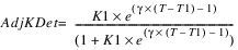
T1 is the value in the Detritus Parameter, Temp 1 column. AdjKDet returns a value between 0.0 and 1.0.
Slots With Required Known Data
• Detritus Parameters
Returns a unit-less dissolved organics decay correction factor based on reservoir temperature and S-curve data. Inputs include a dissolved organics decay rate, and the corresponding temperature. Gamma is calculated with two rates and two temperatures by the calcGamma function (see calcGamma). Current layer temperature is passed in through the variable temp.
(14.29) 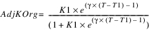
AdjKOrg should return a value between 0.0 and 1.0.
Slots With Required Data
• Dissolved Organics Parameters
Returns a respiration rate correction factor based on reservoir temperature and data from a double S-curve. Inputs include four respiration rates (K1, K2, K3, K4), and the corresponding temperatures (T1, T2, T3, T4). Gamma1 and gamm2 are calculated with two rates and two temperatures by the calcGamma function (see calcGamma). Current layer temperature is passed in through the variable temp. This general function is used to calculate the temperature adjustment factor, AdjK.
(14.30) 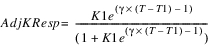
Slots With Required Known Data
• Respiration Parameters
Returns a unit-less sediment oxygen demand correction factor based on reservoir temperature and S-curve data. Inputs include a sediment oxygen demand, and the corresponding temperature. Gamma is calculated with two rates and two temperatures by the calcGamma function (see calcGamma). Current layer temperature is passed in through the variable temp.
(14.31) 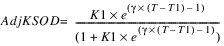
AdjKSOD should return a value between 0.0 and 1.0.
Slots With Required Known Data
• SOD Parameters
Calculates the ammonia balance for the epilimnion and the hypolimnion based on explicit one-step method.
Slots With Required Known Data
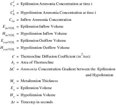
• Ammonia Concentrations—This method requires a previous epilimnion ammonia concentration and a previous hypolimnion ammonia concentration; both are columns on the Ammonia Concentration Agg Series Slot.
• Outflow from Epilimnion
• Epilimnion Volume
• Outflow from Hypolimnion
• Hypolimnion Volume
• Thermocline Diffusion Coefficient
• Inflow to Epilimnion
• Thickness of Epilimnion
• Inflow to Hypolimnion
• Thickness of Metalimnion
Slots With Output Data
• Ammonia Concentrations—This method sets epilimnion ammonia concentration and hypolimnion ammonia concentration; both are columns on the Ammonia Concentration Agg Series Slot.
Method Details
The epilimnion dissolved organics concentration is calculated as follows:
(14.32) 
The hypolimnion ammonia concentration is calculated as follows:
(14.33) 
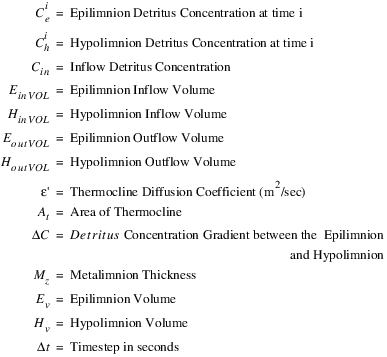
where
This concentration is then adjusted by accounting for ammonia decay. The amount of ammonia decay is used in other functions.These adjustments will be made within a timestep during which the layer volume will be remain constant. Therefore, it is possible to calculate these sources and sinks in terms of concentration instead of mass.
(14.34) 
(14.35) 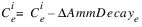
and
(14.36) 
(14.37) 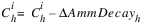
where
It then adjusts the layer ammonia concentrations to account for movement of the thermocline during the timestep.
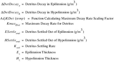
Calculates the detritus balance for the epilimnion and the hypolimnion based on explicit one-step method.
Slots With Required Known Data
• Detritus Concentrations—This method requires a previous epilimnion detritus concentration and a previous hypolimnion detritus concentration; both are columns on the Detritus Concentrations Agg Series Slot.
• Outflow from Epilimnion
• Epilimnion Volume
• Outflow from Hypolimnion
• Hypolimnion Volume
• Thermocline Diffusion Coefficient
• Inflow to Epilimnion
• Thickness of Epilimnion
• Inflow to Hypolimnion
• Thickness of Metalimnion
Slots With Output Data
• Detritus Concentrations—This method sets epilimnion and hypolimnion detritus concentrations; which is a column on the Detritus Concentrations Agg Series Slot.
Method Details
The epilimnion detritus concentration is calculated as follows:
(14.38) 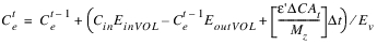
and, the hypolimnion detritus concentration is calculated as follows:
(14.39) 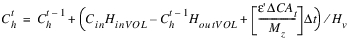
where
This concentration is then adjusted by accounting for detritus decay and settling. The amount of detritus decay is passed out of the function. These adjustments will be made within a timestep during which the layer volume will be remain constant. Therefore, it is possible to calculate these sources and sinks in terms of concentration instead of mass.
(14.40) 
(14.41) 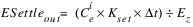
(14.42) 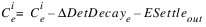
and
(14.43) 
(14.44) 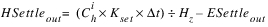
(14.45) 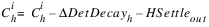
where
It then adjusts the layer detritus concentrations to account for movement of the thermocline during the timestep.
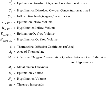
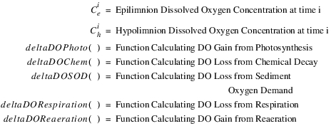
Calculates the dissolved oxygen balance for the epilimnion and the hypolimnion, based on explicit one-step method.
Slots With Required Known Data
• Dissolved Oxygen Concentrations—This method requires a previous epilimnion dissolved oxygen concentration and a previous hypolimnion dissolved oxygen concentration, both are columns on the Dissolved Oxygen Concentrations Agg Series Slot.
• Outflow from Epilimnion
• Epilimnion Volume
• Outflow from Hypolimnion
• Hypolimnion Volume
• Thermocline Diffusion Coefficient
• Inflow to Epilimnion
• Thickness of Epilimnion
• Inflow to Hypolimnion
• Thickness of Metalimnion
Slots With Output Data
• Dissolved Oxygen Concentrations—This method sets the epilimnion dissolved oxygen concentration and hypolimnion dissolved oxygen concentration, both are columns on the Dissolved Oxygen Concentrations Agg Series Slot.
Method Details
The epilimnion dissolved oxygen concentration is calculated as follows:
(14.46) 
and, the hypolimnion dissolved oxygen concentration is calculated as follows:
(14.47) 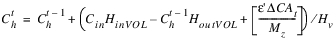
where
This concentration is then adjusted by accounting for photosynthesis, re-aeration, respiration, sediment oxygen demand, and consumption from detritus, dissolved organics, and ammonia decay. These adjustments will be made within a timestep during which the layer volume will be remain constant. Therefore, it is possible to calculate these sources and sinks in terms of concentration instead of mass.
(14.48) 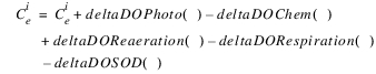
(14.49) 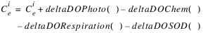
where
It then adjusts the layer dissolved oxygen concentrations to account for movement of the thermocline during the timestep.
Returns a unit-less parameter used to calculate temperature correction factors for sediment oxygen demand, respiration, ammonia decay, dissolved organics decay, and detritus decay. Inputs include two rates (k1, k2), and the corresponding temperatures (t1, t2). Gamma is calculated with the following function:
(14.50) 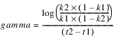
Returns Har (J/(m^2*day), the surface heat flux due to incoming solar radiation, using the following equation (Thomann and Mueller, 1987).
Slots With Required Known Data
• Air Temperature
• Dewpoint Temperature
Method Details
(14.51) 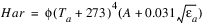
where
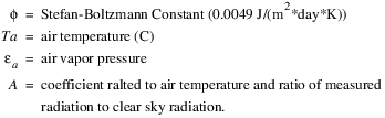
Ta is user input through the Air Temperature slot, and air vapor pressure is returned by the getAirVaporPressure method (see below). The variable, A, is set as follows: if Air Temperature is less than 20(C), A = 0.65, else, A = 0.70.
Returns Hbr (J/(m^2*day), the longwave radiation emitted by the reservoir, using the Stefan-Boltzmann law for a (nearly perfect) black-body emitter.
Slots With Required Known Data
• Temperature—This method requires a previous epilimnion temperature, which is a column on the Temperature Agg Series Slot.
Method Details
(14.52) 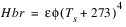
where
The values of the Stefan-Boltzmann constant and emissivity are static variables. Ts is the value of the epilimnion temperature from the previous timestep (epilimnionTemp(‑1)).
Returns Hc (J/(m^2*day), the heat flux at the reservoir surface due to conduction.
Slots With Required Known Data
• Air Temperature
• Wind Velocity
• Temperature—This method requires a previous epilimnion temperature, which is a column on the Temperature Agg Series Slot.
Method Details
The form of the equation is:
(14.53) 
where:
getWindEffect is a utility method (see below) and 41860 is the conversion rate from cal/cm2 to J/m2.
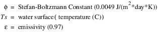
Returns He (J/(m^2*day)), the heat flux at the surface due to evaporative heat loss.
Slots With Required Known Data
• Dewpoint Temperature
• Wind Velocity
• Temperature—This method requires a previous epilimnion temperature, which is a column on the Temperature Agg Series Slot.
Slots With Output Data
• Heat of Evaporation
Method Details
The form of the equation is:
(14.54) 
where
getWindEffect is a utility method and 41860 is the conversion rate from cal/cm2 to J/m2. This function returns He and sets the Heat of Evaporation slot equal to He / 41860.
Calculates the new Temperature for both the epilimnion and hypolimnion based on a backwards-time numerical method.
Slots With Required Known Data
• Epilimnion Volume
• Specific Heat of Water
• Hypolimnion Volume
• Surface Heat Flux
• Inflow to Epilimnion
• Temperature—This method requires a previous epilimnion temperature and a previous hypolimnion temperature; both are columns on the Temperature Agg Series Slot.
• Inflow to Hypolimnion
• Thermocline Diffusion Coefficient
• Outflow from Epilimnion
• Thickness of Epilimnion
• Outflow from Hypolimnion
• Thickness of Metalimnion
Slots With Output Data
• Temperature—This method sets current epilimnion temperature and current hypolimnion temperature; both are columns on the Temperature Agg Series Slot.
Method Details
First, the method calls the selected method in the Surface Heat Flux category to calculate surface flux. The epilimnion temperatures is calculated as follows:
(14.55) 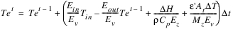
and, the hypolimnion temperatures is calculated as follows:
(14.56) 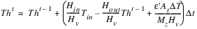
where
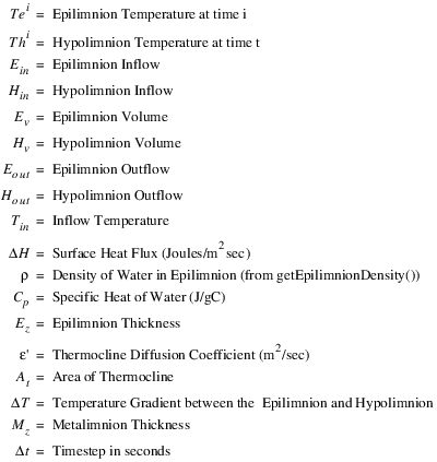
It then adjusts the layer temperatures to account for movement of the thermocline during the timestep and sets the slots.
Calculates the inflow ammonia concentration and total inflow ammonia concentration by doing a weighted average of the inflow and side flow ammonia concentrations. If Canal Flow, Flow FROM Pumped Storage, or Flow TO Pumped Storage are not linked, the associated ammonia contribution is equal to zero.
Slots With Required Known Data
• Ammonia Concentrations—This method requires hydrologic inflow ammonia concentration, a column on the Ammonia Concentrations Agg Series Slot.
• Hydrologic Inflow
• Canal Flow
• Inflow
• Canal Flow Ammonia Conc
• Inflow Ammonia Mass
• Diversion
• Pump Storage Inflow Ammonia
• Diversion Ammonia Conc
• Pump Storage Outflow Ammonia
• Flow FROM Pumped Storage
• Return Flow
• Flow TO Pumped Storage
• Return Flow Ammonia Conc
Slots With Output Data
• Ammonia Concentrations—This method sets inflow ammonia concentration and total inflow ammonia concentration; both are column on the Ammonia Concentrations Agg Series Slot. It uses a similar calculations as calcInflowTemp but sums ammonia mass instead of heat.
Calculates the inflow detritus concentration and total inflow detritus concentration by doing a weighted average of the inflow and side flow detritus concentrations. If Canal Flow, Flow FROM Pumped Storage, or Flow TO Pumped Storage are not linked, the associated detritus contribution is equal to zero.
It uses similar calculations as calcInflowTemp, but sums detritus mass instead of heat.
Slots With Required Known Data
• Canal Flow
• Hydrologic Inflow
• Canal Flow Detritus Conc
• Inflow
• Detritus Concentrations
• Inflow Detritus Mass
• Diversion
• Pump Storage Inflow Detritus
• Diversion Detritus Conc
• Pump Storage Outflow Detritus
• Flow FROM Pumped Storage
• Return Flow
• Flow TO Pumped Storage
• Return Flow Detritus Conc
Slots With Output Data
• Detritus Concentrations
Calculates the inflow dissolved oxygen concentration and total inflow dissolved oxygen concentration by doing a weighted average of the inflow and side flow dissolved oxygen concentrations. If Canal Flow, Flow FROM Pumped Storage, or Flow TO Pumped Storage are not linked, the associated dissolved oxygen contribution is equal to zero.
This method uses similar calculations as calcInflowTemp, but sums dissolved oxygen mass instead of heat.
Slots With Required Known Data
• Canal Flow
• Hydrologic Inflow
• Canal Flow Dissolved Oxygen Conc
• Inflow
• Dissolved Oxygen Concentrations—This method requires hydrologic inflow dissolved oxygen concentration, a column on the Dissolved Oxygen Concentrations Agg Series Slot.
• Inflow Dissolved Oxygen Mass
• Diversion
• Pump Storage Inflow Dissolved Oxygen
• Diversion Dissolved Oxygen Conc
• Pump Storage Outflow Dissolved Oxygen
• Flow FROM Pumped Storage
• Return Flow
• Flow TO Pumped Storage
• Return Flow Dissolved Oxygen Conc
Slots With Output Data
• Dissolved Oxygen Concentrations—This method sets inflow dissolved oxygen concentration and total inflow dissolved oxygen concentration, both are column on the Dissolved Oxygen Concentrations Agg Series Slot.
Calculates the inflow dissolved organics concentration and total inflow dissolved organics concentration by doing a weighted average of the inflow and side flow dissolved organics concentrations. If Canal Flow, Flow FROM Pumped Storage, or Flow TO Pumped Storage are not linked, the associated dissolved organics contribution is equal to zero.
This method uses similar calculations as calcInflowTemp, but sums dissolved organics mass instead of heat.
Slots With Required Known Data
• Canal Flow
• Hydrologic Inflow
• Canal Flow Dissolved Organics Conc
• Inflow
• Dissolved Organics Concentrations
• Inflow Dissolved Organics Mass
• Diversion
• Pump Storage Inflow Organics
• Diversion Dissolved Organics Conc
• Pump Storage Outflow Organics
• Flow FROM Pumped Storage
• Return Flow
• Flow TO Pumped Storage
• Return Flow Dissolved Organics Conc
Slots With Output Data
• Dissolved Organics Concentrations
Calculates the inflow salt concentration and total inflow salt concentration by doing a weighted average of the inflow and side flow salt concentrations. If Canal Flow, Flow FROM Pumped Storage, or Flow TO Pumped Storage are not linked, the associated salt contribution is equal to zero.
Slots With Required Known Data
• Canal Flow
• Inflow
• Canal Flow Salt Conc
• Inflow Salt Mass
• Diversion
• Pump Storage Inflow Salt
• Diversion Salt Concentration
• Pump Storage Outflow Salt
• Flow FROM Pumped Storage
• Return Flow
• Flow TO Pumped Storage
• Return Flow Salt Conc
• Hydrologic Inflow
• Salt Concentrations—This method requires hydrologic inflow salt concentration, one of the columns on the Salt Concentrations Agg Series Slot.
Slots With Output Data
• Salt Concentrations—This method sets inflow salt concentration and total inflow salt concentration, both are columns on the Salt Concentrations Agg Series Slot. It uses a similar calculations as calcInflowTemp but sums salt mass instead of heat.
Calculates the inflow temperature and total inflow temperature by doing a weighted average of the inflow and side flow temperatures; that is, the method sums the heat coming in.
The method considers the following inflows: Inflow, Hydrologic Inflow Net, Canal Flow, Flow TO Pumped Storage, Flow FROM Pumped Storage, Diversion, and Return Flow. If Canal Flow, Flow FROM Pumped Storage, or Flow TO Pumped Storage are not linked, the associated heat contribution is equal to zero.
Slots With Required Known Data
• Canal Flow
• Inflow Heat
• Canal Flow Temp
• Pump Storage Inflow Temp
• Diversion
• Pump Storage Outflow Temp
• Diversion Temp
• Return Flow
• Flow FROM Pumped Storage
• Return Flow Temp
• Flow TO Pumped Storage
• Specific Heat of Water
• Hydrologic Inflow
• Temperature—This method requires a hydrologic inflow temperature, a column on the Temperature Agg Series Slot.
• Inflow
Slots With Output Data
• Temperature—This method sets the inflow temperature and total inflow temperature, both columns on the Temperature Agg Series Slot.
Method Details
The heat associated with each component is calculated as follows:
(14.57) 
The method then sums the heat as follows:
(14.58) 
And then sets the Inflow Temp and Total Inflow columns on the Temperature slot.
Calculates the volume of both the epilimnion and hypolimnion.
Slots With Required Known Data
• Inflow to Hypolimnion
• Storage
• Outflow from Hypolimnion (current and previous)
Slots With Output Data
• Epilimnion Volume
• Hypolimnion Volume
Method Details
Epilimnion and hypolimnion volumes are calculated as follows:
(14.59) 
(14.60) 
These values are later adjusted in AdjKDet after calculating thermocline movement during the timestep (see AdjKDet).
Calculates the dissolved organics balance for the epilimnion and the hypolimnion, based on explicit one-step method.
Slots With Required Known Data
• Dissolved Organics Concentrations—This method requires a previous epilimnion dissolved organics concentration and a previous hypolimnion dissolved organics concentration; both are columns on the Dissolved Organics Concentrations Agg Series Slot.
• Outflow from Epilimnion
• Epilimnion Volume
• Outflow from Hypolimnion
• Hypolimnion Volume
• Thermocline Diffusion Coefficient
• Inflow to Epilimnion
• Thickness of Epilimnion
• Inflow to Hypolimnion
• Thickness of Metalimnion
Slots With Output Data
• Dissolved Organics Concentrations—This method sets epilimnion dissolved organics concentration and hypolimnion dissolved organics concentration; both are columns on the Dissolved Organics Concentrations Agg Series Slot.
Method Details
The epilimnion dissolved organics concentration is calculated as follows:
(14.61) 
and, the hypolimnion dissolved organics concentration is calculated as follows:
(14.62) 
where
This concentration is then adjusted by accounting for dissolved organics decay. The amount of dissolved organics decay is passed out of the function. These adjustments will be made within a timestep during which the layer volume will be remain constant. Therefore, it is possible to calculate these sources and sinks in terms of concentration instead of mass.
(14.63) 
(14.64) 
and
(14.65) 
(14.66) 
where
It then adjusts the layer dissolved organics concentrations to account for movement of the thermocline during the timestep.
Calculates the outflow ammonia concentration and outflow ammonia mass given the epilimnion and hypolimnion outflows, the total outflow, and the epilimnion and hypolimnion concentrations at (t‑1).
Note: As described in the Note in the AdjKDet topic (see AdjKDet), this is an explicit solution. The slot Outflow Ammonia Concentration is set by this method, as the weighted average of the epilimnion and Hypolimnion Outflow and ammonia concentrations.
Slots With Required Known Data
• Ammonia Concentrations—This method requires a previous epilimnion ammonia concentration and a previous hypolimnion ammonia concentration; both are columns on the Ammonia Concentrations Agg Series Slot.
• Outflow from Epilimnion
• Outflow
• Outflow from Hypolimnion
Slots With Output Data
• Ammonia Concentrations—This method sets the outflow ammonia concentration, which is a column on the Ammonia Concentrations Agg Series Slot.
• Outflow Ammonia Mass
Calculates the outflow detritus concentration and outflow detritus mass given the epilimnion and hypolimnion outflows, the total outflow, and the epilimnion and hypolimnion concentrations at (t‑1).
Note: As described in the Note in the AdjKDet topic (see AdjKDet), this is an explicit solution. The slot Outflow Detritus Concentration is set by this method, as the weighted average of the epilimnion and hypolimnion outflows and detritus concentrations.
Slots With Required Known Data
• Detritus Concentrations—This method requires a previous epilimnion detritus concentration and a previous hypolimnion detritus concentration; both are columns on the Detritus Concentrations Agg Series Slot.
• Outflow from Epilimnion
• Outflow
• Outflow from Hypolimnion
Slots With Output Data
• Detritus Concentrations—This method sets the outflow detritus concentration, which is a column on the Detritus Concentrations Agg Series Slot.
• Outflow Detritus Mass
Calculates the outflow dissolved oxygen concentration and outflow dissolved oxygen mass given the epilimnion and hypolimnion outflows, the total outflow, and the epilimnion and hypolimnion concentrations at (t‑1).
Note: As described in the Note in the AdjKDet topic (see AdjKDet), this is an explicit solution. The slot Outflow Detritus Concentration is set by this method, as the weighted average of the epilimnion and hypolimnion outflows and dissolved oxygen concentrations.
Slots With Required Known Data
• Dissolved Oxygen Concentrations—This method requires a previous epilimnion dissolved oxygen concentration and a previous hypolimnion dissolved oxygen concentration; both are columns on the Dissolved Oxygen Concentrations Agg Series Slot.
• Outflow from Epilimnion
• Outflow
• Outflow from Hypolimnion
Slots With Output Data
• Dissolved Oxygen Concentrations—This method sets the outflow dissolved oxygen concentration; which is a column on the Dissolved Oxygen Concentrations Agg Series Slot.
• Outflow Dissolved Oxygen Mass
Calculates the outflow dissolved organics concentration and outflow dissolved organics mass given the epilimnion and hypolimnion outflows, the total outflow, and the epilimnion and hypolimnion concentrations at (t‑1).
Note: As described in the AdjKDet topic (see AdjKDet), this is an explicit solution. The slot Outflow Detritus Concentration is set by this method, as the weighted average of the epilimnion and hypolimnion outflows and dissolved organics concentrations.
Slots With Required Known Data
• Dissolved Organics Concentrations
• Outflow from Epilimnion
• Outflow
• Outflow from Hypolimnion
This method requires a previous epilimnion dissolved organics concentration and a previous hypolimnion dissolved organics concentration; both are columns on the Detritus Organics Concentrations Agg Series Slot.
Slots With Output Data
• Dissolved Organics Concentrations—This method sets the outflow dissolved organics concentration which is a column on the Detritus Concentrations Agg Series Slot.
• Outflow Dissolved Organics Mass
Calculates the outflow salt concentration and outflow salt mass given the epilimnion and hypolimnion outflows, the total outflow, and the epilimnion and hypolimnion concentrations at (t‑1).
Note: As described in the Note in the AdjKDet topic (see AdjKDet), this is an explicit solution. The slot Outflow Salt Concentration is set by this method, as the weighted average of the epilimnion and hypolimnion outflows and salt concentrations.
Slots With Required Known Data
• Outflow
• Outflow from Hypolimnion
• Outflow from Epilimnion
• Salt Concentrations—This method requires a previous epilimnion salt concentration and a previous hypolimnion salt concentration; both are columns on the Salt Concentrations Agg Series Slot.
Slots With Output Data
• Salt Concentrations—This method sets the outflow salt concentration which is a column on the Salt Concentration Agg Series Slot.
• Outflow Salt Mass
Calculates the outflow temperature and outflow heat given the Outflow from Epilimnion, Outflow from Hypolimnion, the total outflow, and the epilimnion and hypolimnion temperatures at (t‑1).
Note: As described in the Note in the AdjKDet topic (see AdjKDet), this is an explicit solution. The slot Outflow Temperature is set by this method, as the weighted average of the epilimnion and hypolimnion outflows and temperatures.
Slots With Required Known Data
• Outflow
• Outflow from Hypolimnion
• Outflow from Epilimnion
• Temperature—This method requires a previous epilimnion temperature and a previous hypolimnion temperature, both are columns on the Temperature Agg Series Slot.
Slots With Output Data
• Outflow Heat
• Temperature—This method sets the outflow temperature, which is column on the Temperature Agg Series Slot.
Calculates the salt balance for the epilimnion and the hypolimnion, based on explicit one-step method. Slots with Required Known Data
• Epilimnion Volume
• Outflow from Hypolimnion
• Hypolimnion Volume
• Salt Concentrations—This method requires previous epilimnion and hypolimnion salt concentrations; both are columns on the Salt Concentrations Agg Series Slot.
• Inflow to Epilimnion
• Thermocline Diffusion Coefficient
• Inflow to Hypolimnion
• Thickness of Epilimnion
• Outflow from Epilimnion
• Thickness of Metalimnion
Slots With Output Data
• Salt Concentrations—This method sets epilimnion and hypolimnion salt concentrations; both are columns on the Salt Concentrations Agg Series Slot.
Method Details
The epilimnion salt concentration is calculated as follows:
(14.67) 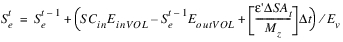
and the hypolimnion salt concentration is calculated as follows:
(14.68) 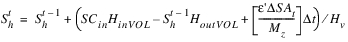
where
It then adjusts the layer salt concentrations to account for movement of the thermocline during the timestep and sets the slots.
Returns surface area for a an elevation based on an approximation of a very small incremental change in the elevation (0.1m) of the reservoir related to the corresponding change in the reservoir volume.
(14.69) 
This function is used only if the Elevation Area Table is not in use because an evaporation method has not been selected.
Slots With Required Known Data
• Elevation Volume Table
Checks detritus, ammonia, dissolved organics, and dissolved oxygen concentrations associated with side flows and sets them if appropriate. Diversion concentrations, negative canal flow concentrations, and pumped storage outflow concentrations are set to previous epilimnion concentrations. If return flow concentrations, positive canal flow concentrations, or pumped storage inflow concentrations are not valid, the method is exited so that the other object can solve first and propagate a concentration across the link.
Checks salt concentrations associated with side flows and sets them if appropriate. Diversion Salt Concentration, negative Canal Flow Salt Concentration, and Pumped Storage Outflow Salt Concentration are set to previous epilimnion salt concentration. If Return Flow Salt Concentration, positive Canal Flow Salt Concentration, or Pumped Storage Inflow Salt Concentration are not valid, the method is exited so that the other object can solve first and propagate a concentration across the link.
Checks temperatures associated with side flows and sets them if appropriate. Diversion Temperature, negative Canal Flow Temperature, and Pumped Storage Outflow Temperature are set to previous epilimnion temperature. If Return Flow Temperature, positive Canal Flow Temperature, or Pumped Storage Inflow Temperature are not valid, the method is exited so that the other object can solve first and propagate a temperature across the link.
Calculates a cubic fit to the elevation - storage relationship of a reservoir given an elevation volume table. This method is currently used by the calcOutflowDistribution method, which applies the coefficients in determining a withdrawal cone at the reservoir outlet works.
Slots With Required Known Data
• Elevation Volume Table
Slots With Output Data
• Reservoir Geometry Coefficients Table—This method uses a Gauss-Jordan method for fitting cubic function to Elevation Volume table values and places results in Reservoir Geometry Coefficients Table slots.
Returns doChem [g/m3], the amount of dissolved oxygen loss due to detritus, dissolved organics, and ammonia decay during the timestep.
Slots With Required Known Data
• Detritus Parameters—This method requires an oxygen stoichiometric coefficient for detritus (rDet [M/M]).
• Ammonia Parameters—This method requires an oxygen stoichiometric coefficient for ammonia (rAmm [M/M]).
• Dissolved Organics Parameters—This method requires an oxygen stoichiometric coefficient for dissolved organics (rOrg [M/M]).
Method Details
The values detritusDecay, dissolvedOrganicsDecay, and ammoniaDecay are passed in from the calling function, calcDO, and represent the values for either the epilimnion or hypolimnion.
The value, doChem is calculated as follows:
(14.70) 
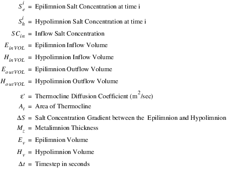
Returns doPhoto [g/m3], the amount of dissolved oxygen gained due photosynthesis during the timestep.
Slots With Required Known Data
• Elevation of Thermocline
• Reservoir Bottom Elevation
• Photosynthesis Parameters
• Thickness of Epilimnion
• Pool Elevation
Method Details
Temperature is the layer’s temperature and is passed in to the method. The depthFromSurface is calculated based on Pool Elevation, Elevation of Thermocline, and Thickness of Epilimnion.
The method returns the following values:
(14.71) 
where
(14.72) 
and
(14.73) 
Returns doReaer [g/m3], the amount of dissolved oxygen gained due to re-aeration during the timestep.
Slots With Required Known Data
• Salt Concentrations
• Wind Velocity
• Thickness of Epilimnion
Method Details
The method returns the following:
(14.74) 
where Kreaer is the surface transfer coefficient
(14.75) 
and Cs is the saturation concentration of dissolved oxygen.
(14.76) 
Temperature of the layer is passed in through layerTemp. If salinity is modeled, the reduced saturation concentration of dissolved oxygen is calculated with the following equation:
(14.77) 
where Css is the new saturation concentration, and S is the salinity concentration in ppt.
Returns doResp [g/m3], the amount of dissolved oxygen loss due to macrophyte respiration the timestep.
Slots With Required Known Data
• Respiration Parameters
Method Details
The method returns doResp, which is calculated as follows:
(14.78) 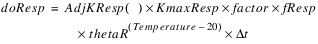
where KmaxResp is the maximum sediment oxygen demand, AdjKResp is a function that calculates a scaling factor to adjust the maximum SOD for the current temperature based on a double S-curve. Factor is a unit-less adjustment ratio for KmaxResp set in calcDO, fResp is an additional calibration knob for sediment oxygen demand. Temperature of the layer is passed into the method.
Returns doSOD [g/m3], the amount of dissolved oxygen loss due sediment oxygen demand during the timestep.
Slots With Required Known Data
• Epilimnion Volume
• SOD Parameters
• Hypolimnion Volume
Method Details
The method returns doSOD, which is calculated using the following equation:
(14.79) 
where KSODMax is the maximum sediment oxygen demand, AdjKSOD is a function that calculates a scaling factor to adjust the maximum SOD for the current temperature based on an S-curve. Factor is a unit-less adjustment ratio for KSODMax set in calcDO, FSOD is an additional calibration knob for sediment oxygen demand. For the hypolimnion, the sediment area is the area of the thermocline. For the epilimnion, the sediment area is the surface area minus the thermocline area.
Returns Air Vapor Pressure, the vapor pressure of the air mass overlying the reservoir.
(14.80) 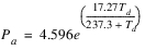
where
Slots With Required Known Data
• Dewpoint Temperature
Returns a weighted average inflow salt concentration for cases where the Inflow Salt Concentration and Inflow have multiple columns of the Multi Slot. The Inflow and Inflow Salt Concentration Multi Slots must have the same number of columns.
Slots With Required Known Data
• Inflow
• Inflow Salt Concentration
Returns Epilimnion water density.
Slots With Required Known Data
• Temperature—This method requires a current or previous epilimnion temperature, a column on the Temperature Agg Series Slot.
Method Details
The value of density for the epilimnion is based on the following polynomial relationship with temperature:
(14.81) 
If this value evaluates to a density greater than 1x10⁶ g/m3, the method returns 1x10⁶ g/m3.
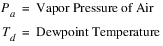
Returns Surface Vapor Pressure, the vapor pressure at the surface of the reservoir:
(14.82) 
where
Slots With Required Known Data
• Temperature—This method requires a previous epilimnion temperature, a column on the Temperature Agg Series Slot.
Returns Coefficient of Wind Effect, the effect of wind on the surface heat flux equations.
(14.83) 
where
Slots With Required Known Data
• Wind Velocity
This method first checks if Diversion is not valid or equal to 0.0. If Diversion Salt Concentration is not valid, Diversion Salt Concentration is set equal to 0.0.
If Diversion is valid or not equal to 0.0, if Diversion Salt Concentration is not valid and Previous Reservoir Salt Concentration is valid, it sets Diversion Salt Concentration equal to the Previous Reservoir Salt Concentration.
Next, the method checks if Return Flow Salt Mass is linked to any object but not valid. If so, the dispatch method exits successfully and control is returned back to the dispatch controller. The object will go back on the queue if Return Flow Salt Mass gets a value.
If Hydrologic Inflow is not valid or it equals 0.0 and Hydrologic Inflow Salt Concentration is not valid, Hydrologic Inflow Salt Concentration is set equal to 0.0. Otherwise, if Hydrologic Inflow is valid or not equal to 0.0, set Hydrologic Inflow Salt Concentration to 0.0 only if it is not valid.
Next, execute the selected Bank Storage Salt method. If no method is selected, set Inbound Bank Storage Salt Mass and Outbound Bank Storage equal to 0.0.
The method checks whether Inflow whether valid, and if it is not equal to 0.0, it sets inflowVol from the inflow rate times the current time step length. Otherwise, inflowVol is set equal to 0.0.
Otherwise, if Hydrologic Inflow, Return Flow, and Diversion are valid, set their local volume variable and set the local variable returnFlowSaltMass to the Return Flow Salt Mass slot. If they are not valid set each to 0.0 along with returnFlowSaltMass.
Then, the function returns to the calling dispatch method to continue with the method.
Calculates a diffusion coefficient for the thermocline calculations.
Slots With Required Known Data
• Pool Elevation
• Thermocline Diffusion Coefficient Adjustment
• Reservoir Bottom Elevation
Slots With Output Data
• Thermocline Diffusion Coefficient
Method Details
Typically, this function is called only if the user has not supplied a coefficient of their own. The value is set by the following equation:
(14.84) 
where
Executes the layered model. It models fluxes of constituents into and out of a reservoir hypolimnion and epilimnion. Figure 14.1 illustrates the general structure.
Figure 14.1 Schematic of two-layer water quality reservoir structure
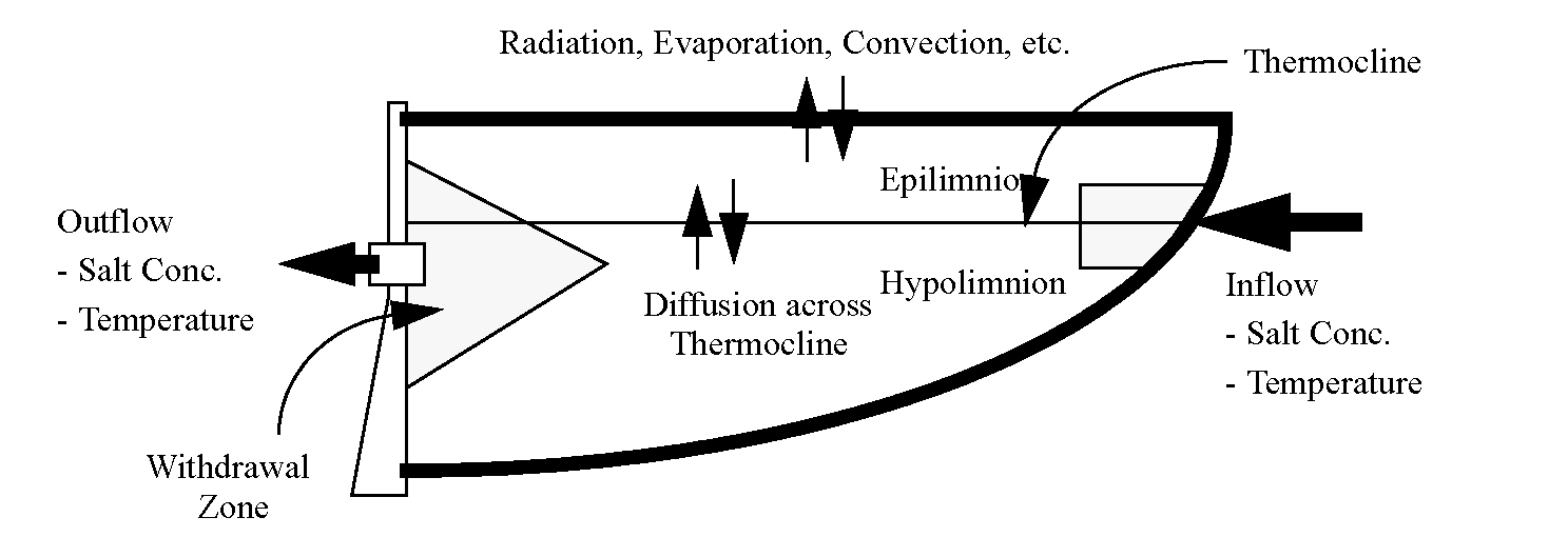
Note: The current WQ_2_Layer model uses a purely explicit approach to solving the reservoir’s water quality balances. That is, all calculations are based (where applicable) on information from the previous timestep. Thus outflow salt concentration is purely a function of the current outflow and the concentrations at the end of the previous timestep (that is, hypolimnion Salt Concentrations(‑1)). This approach eliminates the need for an iterative or simultaneous type of solution, and for larger reservoirs running relatively small timesteps does not compromise the validity of the solution
Slots With Required Known Data
• Inflow
• Inflow Heat
• Inflow Ammonia Mass
• Inflow Salt Concentration
• Inflow Detritus Mass
• Inflow Salt Mass
• Inflow Dissolved Organics Mass
• Outflow
• Inflow Dissolved Oxygen Mass
• Storage
Slots With Output Data
• Ammonia Concentrations
• Outflow Dissolved Organics Mass
• Detritus Concentrations
• Outflow Dissolved Oxygen Mass
• Dissolved Organics Concentrations
• Outflow Heat
• Dissolved Oxygen Concentrations
• Outflow Salt Mass
• Outflow Ammonia Mass
• Salt Concentrations
• Outflow Detritus Mass
• Temperature
Method Details
The methods associated with this structure are outlined below. The methods are nested; that is, many methods rely on submethods for pieces of their functionality. For example, the default CalcSurfaceFlux user method relies on output from the calcHar, calcHbr, calcHc, and calcHe utility methods. Description below depict the nested nature of the temperature and salt solver in the water quality controller. The sequence of functions represents the order of execution, and the offset represents the nesting of the methods within “parent” methods. The WQ_2_Layer method does the following in order:
Verify that there is a valid previous Hypolimnion Volume and that it does not equal zero. If there is not use the previous pool elevation to calculate the previous Hypolimnion volume using the Epilimnion Thickness. Verify there is a valid previous Epilimnion Volume and Thermocline Elevation. If not, calculate these using the Hypolimnion Volume and Epilimnion Thickness.
Next determine the surface area of the reservoir and surface area of the thermocline using the Elevation Area table (if valid) or the calcSurfaceArea function.
• If modeling temperature, call calcInflowTemp.
• If modeling salinity, call calcInflowSaltConc.
• If modeling dissolved oxygen, call calcInflowDOConc, calcInflowDetConc, calcInflowOrgConc, and calcInflowAmmConc.
Execute the selected DistributeInflowCategory and DistributeOutflowCategory method.
Calculate the outflow concentration for each constituent. This can be done now since the modeling scheme is explicit. If Outflow is zero, set the Outflow Concentration of each constituent to zero.
• If modeling temperature calcOutflowTemp
• If modeling salinity, calcOutflowSaltConc
• If modeling dissolved oxygen, calcOutflowDOConc, calcOutflowDetConc, calcOutflowOrgConc, and calcOutflowAmmConc.
Call calcLayerVolumes to determine the volume in each layer.
Find the change in volume between layers due to thermocline movement during timestep. Determine the new HypolimnionVolumne and Epilimnion Volume due to this movement.
Determine the final concentration of the constituent in the reservoir:
• If modeling temperature, calcHeat
• If modeling salinity, calcSalt
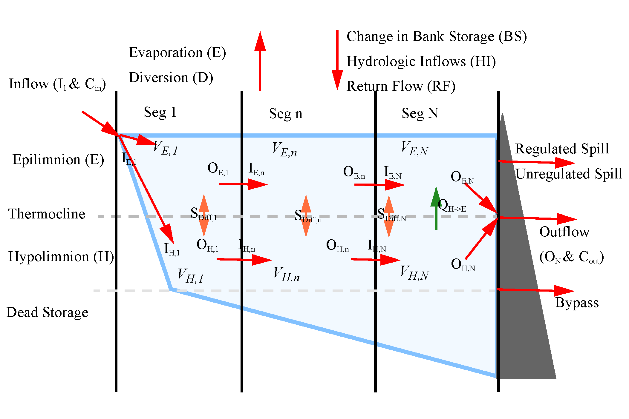
Executes the segmented two-layered model. Salt is modeled as it flows through each segment in both the epilimnion and hypolimnion. The general structure is shown in the following figure. The reservoir object has N longitudinal segments and two vertical layers, the epilimnion and hypolimnion. Segment 1 represents the segment where water flows into the reservoir; Segment n represents zero or more interior segments, and Segment N represents the outflow segment. The number of longitudinal segments and the sizes are specified by the user.
When first configuring the method, the user should set the Number of Segments slot and initialize a run. The run will error, but RiverWare will update the Agg Series and Table slots with the correct number of segments. Then, the user can add necessary data to these slots.
In this approach, the thickness of the hypolimnion layer is constant and the elevation of the thermocline is constant, unless the pool elevation drops below the thermocline elevation. Each mass balance component except Evaporation will have an equivalent salt concentration and salt mass component. On the Reservoir object, the Change in Bank Storage and Vertical Flow from Hypolimnion to Epilimnion can be either negative or positive. The salt concentration entering the reservoir comes from a linked slot or is specified (input or rules).
The water mass balance is calculated by existing quantity Dispatch Methods. Once the water quality methods dispatch, this method will calculate a flow balance inside the reservoir now accounting for the layers and segments. The inflow flowing into the hypolimnion and epilimnion and outflow flowing from the hypolimnion and epilimnion is specified with a periodic or series fractional relationship. The salinity balance can then be calculated using the flow balance and a diffusion term to transport salt between the hypolimnion and epilimnion. Concentration in each segment, layer, in the bank storage, diversions, return flow and outflow are calculated each timestep.
Figure 14.2
Note: The current WQ_Segmented_2_Layer model uses a purely explicit approach to solving the reservoir’s water quality balances.
Slots With Required Known Data
• Inflow
• Inflow Salt Concentration
• Outflow
• Inflow Salt Concentration
• Storage
• Number of Segments
• Segment Parameters Table
• Dead Storage by Segment
• Elevation Volume Table by Segment
• Elevation Area Table by Segment
• Thermocline Elevation
• Thermocline Diffusivity
• Thermocline Thickness
Slots With Output Data
• Outflow Salt Concentration
• Outflow Salt Mass
• Epilimnion Salt Conc by Segment
• Epilimnion Salt Mass by Segment
• Hypolimnion Salt Conc by Segment
• Hypolimnion Salt Mass by Segment
• Inflow to Hypolimnion
• Outflow from Hypolimnion
• Inflow to Epilimnion
• Outflow from Epilimnion
• Epilimnion Volume by Segment
• Hypolimnion Volume by Segment
• Epilimnion Inflow by Segment
• Epilimnion Outflow By Segment
• Hypolimnion Outflow by Segment
• Hypolimnion Inflow by Segment
• Vertical Flow
• Bank Storage by Segment
• Diversion by Segment
• Return Flow by Segment
• Hydrologic Inflow by Segment
• Evaporation by Segment
• Precipitation by Segment
Method Details
Following is a conceptual overview of the computation to determine storage, salt concentration, and flow in, out, and between each segment and layer. Once the water balance is calculated by existing RiverWare functions, these steps can be completed. Each step will check if the pool elevation is below the thermocline elevation. When the pool elevation is above the thermocline, the reservoir is composed of two layers, the epilimnion and hypolimnion. If the pool elevation is below than the thermocline elevation, there will only be one layer in the reservoir, the hypolimnion. All inflows and outflows will enter and leave the hypolimnion. There will be no vertical flows, and the evaporation and bank storage will affect the hypolimnion, not the epilimnion.
Following are the conceptual steps taken in a run. These computations are described in detail in the following sections.
1. Determine the layer and segment volumes based on the water elevation.
2. Determine the inflow into each layer and outflow from each layer using the specified fraction.
3. Compute the evaporation from each segment and precipitation entering each segment using the Elevation Area Table by Segment.
4. Compute the vertical flow by taking the difference between the outflow and inflow.
5. Compute the proportion of bank storage, return flow, diversions, and hydrologic inflow entering and leaving each segment by using values in the Segment Parameters Table.
6. Compute the inflow for each epilimnion segment by adding together segment outflows, change in storage, vertical flow, evaporation and subtracting the change in bank storage.
7. Compute the inflow for each hypolimnion segment by subtracting the vertical flow from the segment outflow.
The water balance is complete. The following steps describe computations for salinity.
1. Compute the salt concentration in the bank storage.
2. Compute the salt mass and concentration in the epilimnion and hypolimnion for each segment and layer using the flows calculated from the water balance and an additional diffusion term.
3. Compute the outflow salt mass and concentration. Outflow salt concentration is based on current concentration.
4. Compute total reservoir salt mass.
The following sections describe these steps in detail.
Determine Storage in each Segment and Layer
The storage in each layer and segment is determined at the current timestep using the pool elevation (PE), thermocline elevation (TE), and Elevation Volume Table by Segment. The dead storage is added into the hypolimnion volume.
For each segment n,
(14.85) 
(14.86) 
Compute Inflow to each Layer and Outflow from each Layer
The inflow to the hypolimnion and epilimnion and outflow from the hypolimnion and epilimnion are calculated through the WQ Distribute Outflow and WQ Distribute Inflow methods. The methods calculate flow distribution between the two layers for reservoir inflow and outflow.
Compute Evaporation and Precipitation From Each Segment
The evaporation leaving each segment and the precipitation entering each segment is based on the proportion of total surface area in each segment. The proportion of total surface area in each segment is calculated using the Elevation Area Table by Segment. The following equations calculate the evaporation and precipitation in each segment, n.
(14.87) 
(14.88) 
Compute Bank Storage, Hydrologic Inflow, Diversion, and Return Flow for Each Segment
The bank storage, hydrologic inflow, diversion, and return flow entering or leaving each segment is calculated using the Segment Parameters Table. The proportions for each flow component are constant. The following equations calculates the bank storage, hydrologic inflow, diversion, and return flow affecting each segment.
(14.89) 
(14.90) 
(14.91) 
(14.92) 
Compute Vertical Flow From Hypolimnion to Epilimnion
The vertical flow is the difference between the hypolimnion inflow and outflow. The vertical flow moves excess water enter the hypolimnion to the epilimnion to keep the hypolimnion at a constant volume. The vertical flow only occurs in the segment closest to the dam, since there is no physical mechanism for vertical flow in other segments. If the pool elevation is below the thermocline, there is no vertical flow. From the conditions described above, the vertical flow is computed as follows:
If PE(t) > Thermocline Elev AND PE(t‑1) > Thermocline Elev
(14.93) 
(14.94) 
Else
(14.95) 
Check Inflow and Outflow Layer
The inflow and outflow layer of the reservoir is computed above in WQ Distribute Outflow and WQ Distribute Inflow. The inflow and outflow layer must be checked to ensure water can flow in or out of the epilimnion. All inflows and outflows only enter and leave the hypolimnion if the pool elevation is below the thermocline. If the spillways are in use, the flow through the spillways must be removed from the correct layer. Unregulated and regulated spill outflows from the epilimnion, and bypass outflows from the hypolimnion. The inflows and outflows are checked and reset as follows:
If spill(t) < 0
(14.96) 
(14.97) 
If PE(t) < Thermocline Elev
(14.98) 
(14.99) 
(14.100) 
(14.101) 
If PE(t) > Thermocline Elev AND PE(t‑1) < Thermocline Elev
(14.102) 
(14.103) 
(14.104) 
(14.105) 
Compute Epilimnion Inflows and Outflows
The epilimnion inflows and outflows for each segment are computed using the water balance calculated by existing RiverWare functions. The water balance calculates outflow using the inflow, volume, vertical flow, evaporation, precipitation, hydrologic inflow, diversion, return flow and bank storage. If the pool elevation (PE) is below the thermocline elevation (TE), there will be no water in the epilimnion. The epilimnion inflows and outflows for each segment are computed as follows:
If PE(t) < Thermocline Elev
(14.106) 
(14.107) 
Else (normal scenario)
(14.108) 
(14.109) 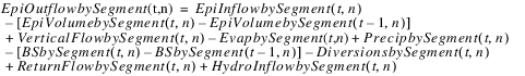
(14.110) 
(14.111)  (check mass balance)
(check mass balance)Compute Hypolimnion Inflows and Outflows
The hypolimnion inflows and outflows for each segment are calculated using a vertical flow and outflow, unless the pool elevation is below the thermocline. When the pool elevation is below the thermocline, the hypolimnion inflows and outflows are calculated similar to the epilimnion inflows and outflows. The hypolimnion inflows and outflows for each segment are computed as follows:
If PE(t) & PE(t‑1) > Thermocline Elev
(14.112) 
(14.113) 
(14.114)  when n=N
when n=N(14.115) 
(14.116)  (check mass balance)
(check mass balance)If PE(t) < Thermocline Elev & PE(t‑1) > Thermocline Elev
(14.117) 
(14.118) 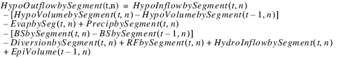
(14.119) 
(14.120)  (check mass balance)
(check mass balance)If PE(t) & PE(t‑1) < Thermocline Elev
(14.121) 
(14.122) 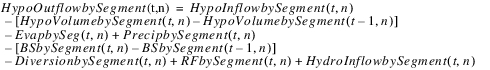
(14.123) 
(14.124)  (check mass balance)
(check mass balance)If PE(t) > Thermocline Elev & PE(t‑1) < Thermocline Elev
(14.125) 
(14.126) 
(14.127) 
(14.128)  (check mass balance)
(check mass balance)The water mass balance is complete after this step. All the inflows, outflows, changes in storage and vertical flows are now known. The salinity mass balance can be calculated with the above information.
Compute Bank Storage Salinity
The bank storage salinity is computed using the previous bank storage salinity and the salinity entering or leaving the bank. When water is entering the bank, salinity mass coming in with the water from the epilimnion affects the concentration in the bank. When water is leaving the bank and entering the reservoir, the salinity mass leaving the bank is added to the epilimnion.
The bank storage salt mass is computed as follows:
If Change in Bank Storage(t) < 0
(14.129) 
If PE(t) > Thermocline Elev & Change in Bank Storage(t) > 0
(14.130) 
If PE(t) < Thermocline Elev & Change in Bank Storage(t) > 0
(14.131) 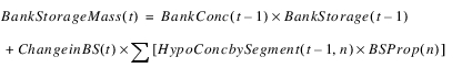
The bank storage salt concentration is computed as follows:
(14.132) 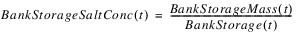
Compute Epilimnion and Hypolimnion Salinity
The epilimnion and hypolimnion salt mass and concentration for each segment are computed from a mass balance on salinity. Water and salinity can flow in or out of the bank storage, up or down vertically between the epilimnion and hypolimnion through diffusion and vertical flow, and in and out of each longitudinal segment. The following equations account for the different flow directions of salinity in the mass balance.
The variables VerticalFlowConc and BSFlowConc must be known before calculating the salinity mass. If an intermediate concentration is computed in the concentration calculations, it will replace the epilimnion or hypolimnion concentrations for the VerticalFlowConc and BSFlowConc variables.
If Vertical Flow(t) > 0
(14.133) 
Else
(14.134) 
If Change in Bank Storage(t) < 0
(14.135) 
If Change in Bank Storage(t) > 0 AND
PE(t) & PE(t‑1) > Thermocline Elev
(14.136) 
Else
(14.137) 
Once the VerticalFlowConc and BSFlowCon variables are known, the salt mass and concentration are calculated based on the pool elevation and thermocline elevation:
If PE(t) < Thermocline Elev & PE(t‑1) > Thermocline Elev
(14.138) 
(14.139) 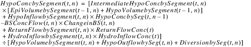
(14.140)  for n=1
for n=1(14.141) 
(14.142) 
(14.143) 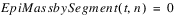
If PE(t) < Thermocline Elevation & PE(t‑1) < Thermocline Elev
(14.144) 
(14.145)  for n=1
for n=1(14.146) 
(14.147) 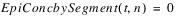
(14.148) 
If PE(t) > Thermocline Elevation & PE(t‑1) > Thermocline Elev
(14.149) 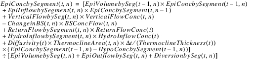
(14.150) 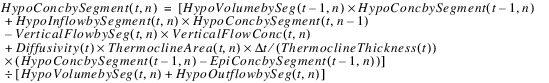
(14.151)  for n=1
for n=1(14.152)  for n=1
for n=1(14.153) 
(14.154) 
Compute Outflow Salinity
The outflow salt mass and concentration is calculated based on the outflow volume, and the epilimnion and hypolimnion concentration in segment N. The following equations calculated the outflow salinity:
(14.155) 
(14.156) 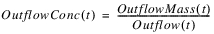
Compute Total Reservoir Salt Mass
The reservoir salt mass is calculated based on the concentration and volume in each segment. The following equations calculated the reservoir salt mass:
(14.157) 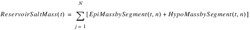
The Segmented Two-layer Salt Reservoir method is complete. The outflow concentration and mass can then be transfered across a link, and water quality in downstream objects can be solved.
Notes for Segmented Two-layer Salt Method
The following parameters can be altered to calibrate the salinity model:
• The number of segments.
• The inflow or outflow distribution fraction of the epilimnion and hypolimnion.
• The Elevation Storage Table by Segment. Try to make the volume in each segment relatively equal.
• The diffusion terms. Change the thermocline thickness and diffusivity.
• Segment proportions for the following flows: diversion, return flow, hydrologic inflows, bank storage.
Revised: 01/10/2022