About the Trace Directory DMI
The Trace Directory Data Management Interface (DMI) is similar to the Control File-Executable approach where the user develops a control file that specifies the slot data to move into or out of RiverWare. However, instead of an executable, the user specifies a top directory, under which the data files for traces are accessed in subdirectories named with the trace number.
The Trace Directory DMI provides a means to transfer data between RiverWare and data files in a known directory structure. There are two directions in which the DMI can transfer data:
• An Input DMI transfers data from data files into RiverWare.
• An Output DMI transfers data from RiverWare into data files.
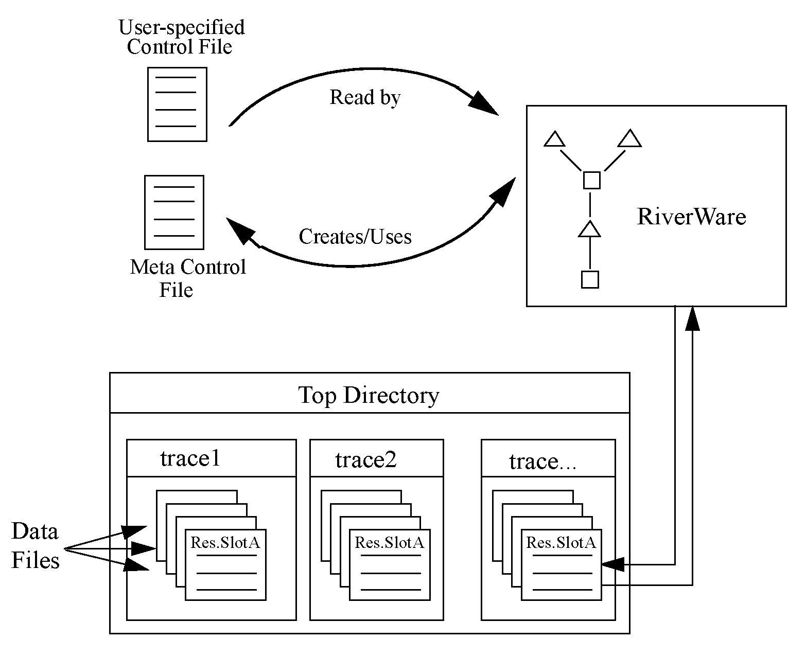
The Trace Directory DMI consists of several components. Figure 3.1 illustrates the relationships among these components.
Figure 3.1 Trace Directory DMI components

• The user-specified Control File is created by the user and contains a list of slots which the user wants imported or exported from the RiverWare model. The control file is an ASCII file which can map data between object.slot names in the Workspace and data file names. See Control File for details. But no file= needs to be specified as the Trace Directory DMI can resolve the file name from the trace directory path and the object.slot name. The control file could be as simple as the following entry:
BigRes.Outflow: units=cfs scale=1
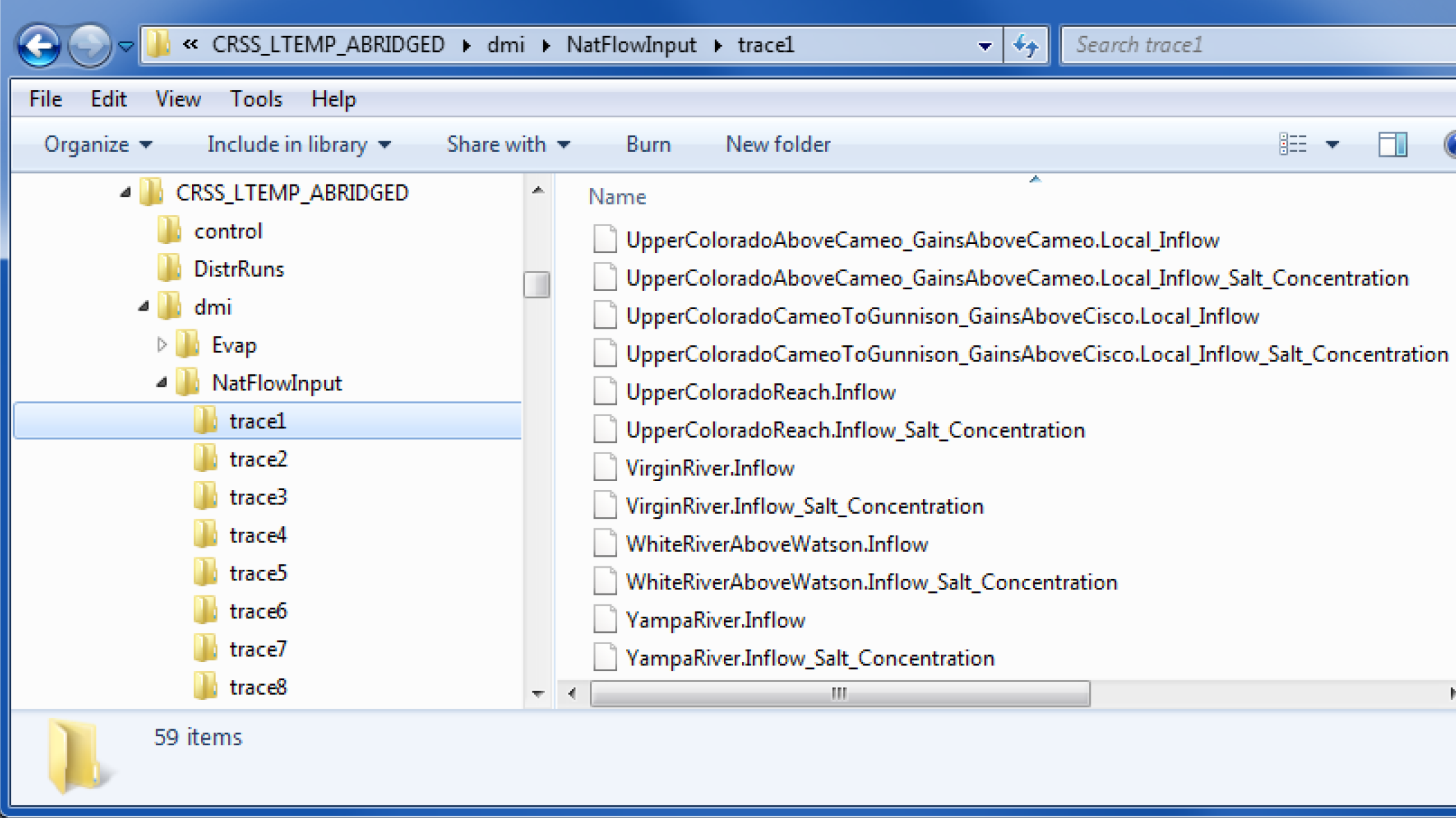
• The user-specified top directory is a directory under which data files will be located within subdirectories named with the trace number corresponding to the data (i.e. trace1, trace2, etc.) Multiple traces could be associated with input or output DMIs from multiple runs, but running a Trace Directory DMI outside of MRM would use a single trace folder. Figure 3.2 is an example of a top directory (NatFlowInput) and trace subdirectories, each of which contains slot data files.
Figure 3.2

• The RiverWare DMI data files are a set of files used to transfer the data to and from the RiverWare model. Each of these files contains the data for a single slot in the model. In an output DMI RiverWare will create the files, or will read existing files for an input DMI. See Data Files for details.
Following is an example of how the DMI works. In this example we assume it is an Input DMI, but it is the same, just reversed for an Output DMI.
1. The user Invokes the Input DMI.
2. RiverWare verifies the DMI to make sure it is valid.
3. RiverWare reads the user Control File and resolves all wild carding. It then substitutes the directory path for the current trace into the file keyword path for each entry in the control file. If a file keyword is not provided, it generates one from the trace directory path and the object.slot name. It then writes the Meta Control File, which has a fully specified line for each slot in the Control File.
4. RiverWare then uses the Meta Control File to read the DMI Data Files from their appropriate directory and imports the data into the slots in RiverWare.
Revised: 01/05/2024